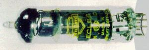

Bottom view. NJ7P Database
|
http://www.ozvalveamps.org/6gw8generic.html | Last update:
00:39 23/11/06
<<< OzValveAmps |
The 6GW8 is a 9-pin high-mu triode and sharp-cutoff pentode in the same envelope. It is identical to the European type ELC86[*] and characteristically the same as the PCL86 (which has a higher voltage heater). The triode section is similar to half a 12AX7.
[* E = 6.3V heater, P = 14.5V, L = pentode, C = triode]
This valve is very commonly found in smaller practice-class Aussie amps of the later era. Like the EL34 these seem to still be in production and traders such as WES Components carry NNS (New New Stock).
Used as triode preamp to single-ended pentode in low power applications such as portable record players.
Pentode
Plate Voltage ................................. 300 Volts
Grid No. 2 Voltage ............................ 300 Volts
Plate Dissipation ............................. 9 Watts
Grid No. 2 Dissipation ........................ 1.5 Watts

Pentode Class A Amplifier
Plate Voltage ................................. 250 Volts
Grid No. 2 Voltage ............................ 250 Volts
Grid No. 1 Voltage ............................ -7 Volts
mu ............................................ 21
Plate Resistance (approx) ..................... 45K Ohms
Transconductance .............................. 10000 MicroMhos (10mA/V)
Plate Current (Zero Signal) ................... 36 Ma.
Grid No. 2 Current (Zero Signal) .............. 6 Ma.

Triode Class A Amplifier
Plate Voltage ................................. 250 Volts
Grid No. 1 Voltage ............................ -1.9 Volts
mu ............................................ 100
Transconductance .............................. 1600 MicroMhos (1.6mA/V)
Plate Current (Zero Signal) ................... 1.2 Ma.

Vh = 6.3 Volts (6GW8 and ECL86 only)
Ih = 660 Ma
Vh-k = 100Vpk
Vh = 14.5 Volts (PCL86 only)
Ih = 300 mA

Maximum (limiting) ratings

Plate supply ............ 550 V
Plate voltage ........... 300 V
G2 supply ............... 550 V
G2 voltage .............. 300 V
Cathode current (avg) ... 4 mA (T), 55 mA (P)
G2 input ................ 1.8 W (3.25 Wpk)
Plate dissipation ....... 0.5 W (T), 9 W (P)
G1 circuit R (max) ...... 1M (T), 500K (P)
The capacitance between triode grid and pentode anode (CgT-aP) can be reduced to a value of less than 0.002pF by using a shielding ring with a diameter of 22.5 mm and a height of 15 mm with respect to the tube base.
Triode section as AF amplifier
New: 28/9/06
Supply voltage Vb 200 250 250 300 V Cathode resistor Rk 2.6 1.75 1.75 1.2 Kohm Anode resistor Ra 220 220 220 220 Kohm Next grid resistor Rg' 0.68 0.68 10 10 Mohm Anode current Ia 0.42 0.6 0.6 0.8 mA Output voltage Vo/Vi 66 70 75 80 (times) Distortion dtot 0.6 0.4 0.4 0.4 % Pentode section Class-A (with Vk constant)
Anode voltage Va 250 250 250 250 250 250 V Grid 2 voltage Vg2 250 250 250 250 250 250 V Cathode resistor Rk 7 7 7 10 10 10 Kohm Grid 1 drive Vg1 0 0.3 3.2 0 0.28 2.7 Vrms Anode current Ia 36 - 37 26 - 27 mA Grid 2 current Ig2 6 - 10.2 4.4 - 8.0 mA Output power Wo 0 0.05 4.0 0 0.05 2.8 W Pentode section Class-AB1 two tubes in push-pull
G2 currents corrected 9/10/06
Supply voltage Vb 250 250 250 300 300 300 Volts Common cathode resistor Rk 90 90 90 130 130 130 ohm Load resistance Ra-a~ 8.2 8.2 8.2 9.1 9.1 9.1 Kohm Grid 1 drive Vi 0 0.24 5.5 0 0.26 8.4 Rrms Anode current Ia 2x32.5 - 2x35.5 2x31 - 2x36.5 mA Grid 2 current Ig2 2x5.6 - 2x8.9 2x5.5 - 2x11 mA Output power Wo 0 0.05 10 0 0.05 13.6 W Distortion dtot - 0.4 5.0 - 0.4 4.0 % Characteristic curves for pentode, triode-strapped pentode, and the triode section. (about 50k gif each) Source: jk1eyp (in Japanese, go via Google for “translation”)
New: 12/03/06

Circuit tracing of single-ended 6GW8 NoName amp bought on e-bay by Neil M.
New: 28/9/06
Notes: screens Ultra-Linear connected; MJE340 is a commonly available high voltage transistor used here as a capacitance multiplier (the 100uF on the base is multiplied by the transistor hFE or gain). Each cathode bypass is 2,200uF for extended (hi-fi) bass. The RC “snubbers” on the transformer windings may require tweeking for individual output transformers, also the 0.002uF in the Voltage NFB loop. Vsup = 330V, RL = 12k p-p, Pout = 10W (hi-fi).
New: 28/9/06
Notes: screens fed by common 470 ohm dropper resistor. Fixed -6.6V bias. Phase inverter stage is of the inverting-amplifier type, unusually, taking its input from the output transformer secondary. The common tail is a FET current sink to appromimate the ideal case of an infinite resistor connected to an infinitely negative voltage. Vsup = 245V, RL = ? p-p, Pout = 8W (hi-fi)
|
|