The preamp stages are normally powered at minimal current (1 or 2mA per stage) drain from the main HT supply that feeds the output stage, through suitable resistor-electrolytic decoupling networks. So the requirements of the output stage determine the HT supply design.
This HT is distributed to the different stages via a decoupling network of resistors in series, with big electrolytic caps to ground. The idea being to stop unwanted feedback, positive or negative, between stages via the HT line. Note that these front-end decoupling caps may normally operate at a lowish HT voltage but they will be subject to the full unloaded output voltage of the HT supply during warm-up before the valves start drawing current, and must be voltage rated accordingly.
Generally the main HT voltage is between about 250 and 500 volts, and at currents up to several hundred milliamps in a big amplifier.
For the 6GW8, 6BM8 and similar the HT will be between 250 and 300-odd volts at up to about 100mA for a simple amp, to perhaps 250mA for a twin combo fully optioned with multiple preamps, tremolo and reverb at full boogie.
Note: actually the supply of heater current is the key limitation to adding stages.
HT Trannies
In Ye Olde Days we would have simply bought a suitable tranny with a 250-0-250 or 285-0-285 volt winding (with two or three brutal heater windings), add a suitable valve rectifier, and we would be away. But apart from scrounge and specials (made to order), you can't get trannies like this any more. My own Playmaster 117 uses a tranny recovered from a dead B&W 21-inch TV set which is still more than equal to the task, but they haven't built telly's like that for decades.
The whole world has gone solid-state and low voltage/high current, so there is quite a range of such trannies. But as solid-state amps progress, so the required rail voltages have been rising, as high as +/-70 volts in some cases.
When we look for higher voltage transformers we find a rather odd problem; these are also the trannies with the highest power ratings. In most cases they are much more than required, 160 watts and up, and therefore heavy and fairly expensive.
Altronics and Jaycar types. (VA = volt-amps = watts)
M4925, 5025, 5125, and MT2144 are torroids
Back-to-back (serial)
One answer is to take two more sensibly-rated trannies and connect them back-to-back, producing an isolated 250 volt winding. In the SC Mudlark this was done using a couple of torroids.
This has a couple of potential advantages if multi-tapped transformers are used, allowing some adjustment of the final output such as driving a nominally 9 or 15 volts winding from 12 volts for more or less output voltage.
In theory transformers are bi-lateral devices, that is they work the same both ways.
This may be truer of torroids, but most available low-power E-I transformers do not work that well in reverse, in fact they tend to be pretty lossy forwards too but we don't notice.
Having two trannies in cascade doubles the effective series resistance of the supply, reducing its voltage regulation (having more “sag”). Double the weight is also a consideration in a portable amplifier the Mudlark can ignore.
A particular disadvantage is that the entire power for the amplifer has to pass through both, which means for a 60W amp consuming 120W you need two 120VA cores, a total of 240VA of core, copper, and weight for only 60W output.
SMPS - Switch-Mode Power Supplies
At least one article has been published (in Silicon Chimp) on converting a computer power supply to deliver high voltage by rewinding the transformer potcore.
Regulated High-Voltage Supply For Valve Amplifiers
by Leonid Lerner
How to modify a surplus PC power supply to produce a 700V or 400V high-voltage rail.
Silicon Chip, Issue: 190 Published: 28 July, 2004
http://www.siliconchip.com.au
This is a major project in its own right.
It has the advantages of cheapness, low weight, and you can have exactly whatever voltage you desire - regulated.
For my part I think it's simpler to buy a bobbin-wound low voltage tranny of suitable core wattage rating, strip the secondary, and wind my own. It amounts to much the same thing without the complexity (and potential noise radiation) of the SMPS. With fewer bits it may also be more reliable. ;))
Series connection
Well, if we are going to have two trannies for the HT supply, what happens if we use available low-voltage trannies with their secondaries in series to double the initial AC voltage?
For our 60W amp we only need two 60W cores, half the VA of serial or back-to-back connection, because the cores now share the load between them. At least 30% lighter for a better regulated supply.
Voltage multipliers
Another option is to use a voltage-multiplying rectifier. These take the form of capacitor and diode ladders that act as charge pumps. These can be voltage doublers, triplers, quadruplers, and so on. Multiplier-rectifiers have a bad reputation for sagging badly under load, but as we will see, that is undeserved.
The advent of demanding SMPS (above) has produced a new generation of electrolytic capacitors of high voltage, high capacitance, small size, and low ESR or high ripple current rating. These are particularly suited to voltage multiplier applications. And if you scrounge power supplies or disposable cameras they're Free!
Voltage multipliers have been built using valve rectifiers, despite the difficulty obtaining isolated heater supplies, but there are many suitable silicon rectifiers available that allow us to avoid this problem. In fact 1000 volt 1 amp diodes are so cheap they are almost free. If you use scrounged bridges they are Free!
Tie the “AC” leads of a (recovered from dead PC supplies) bridge rectifier together, and call it two diodes in series. But first - test all diodes with your trusty little yellow DVM for about 700 millivolts forward (not shorted) and no reverse leakage at all.
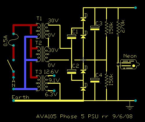
 Notional
 valve amp HT supply
(actual-build details, below)
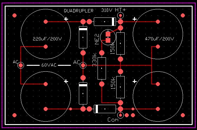
Don't Panic! This is only a simple half-wave rectifier times four, but drawn somewhat differently to what you may be used to. It's two doublers stacked on top of each other and driven in the middle to make a voltage quadrupler. The series resistor is switch-on surge limiting (and some sag), the shunt resistors a safety bleeder. You'll find half of this in many Moody's, and in the Playmaster 102.
Operation
On one half-cycle the first caps in series (left hand) charge up to the transformer peak voltage. On the other half-cycle this pre-charged cap is added to the tranny peak voltage, so charges the second (right-hand) reservoir caps to twice the peak voltage on the tranny winding.
Exactly the same thing is happening below, but in reverse making a minus supply which adds to the output because it it stacked in series with the upper section, thus giving four times the peak winding voltage.
How much charge gets pumped?
Since the pumping rate is fixed by the mains frequency the amount of power this supply can deliver and it's voltage regulation depend a lot on the size of the caps used. I could buy big high-voltage caps, but the caps I've already recovered are 330uF. Will they be big enough?
The charge (Q, in Couloumb) on a cap is;
Q = C x V
...and we are lucky that charge is also simply defined as Amp/seconds past a point;
Q = I x t
[these two relationships are well worth pasting in your hat]
I hope it is obvious therefore that;
C x V = I x t
So we can now relate capacitance, voltage, and current over time. This is bound to be useful.
Voltage Regulation
The regulation of a simple supply is quoted in percentage voltage drop between no-load and full rated load (although the range 10% to 90% load might be more practically meaningful). Most of the small trannies being considered here have a quoted regulation of 5%. In practice this means the rated voltage at the rated current, so the no-load voltage will be somewhat higher, here about 5%.
Voltage multipliers don't have a great reputation for regulation. One of the reasons were the limited capacities and ripple currents available, but modern electrolytic caps have changed that.
Using a 25+25 volt tranny as an example; when un-loaded the first cap will charge to the peak output voltage of the tranny.
This is root(2)=1.414 times the rms value, or around 70 volts. We must remember to subtract the diode voltage drop (~0.7V), but since the output voltage is quoted for full load we can expect a nominal 50 volt tranny to be producing 5% more or about 52.5 volts unloaded, so this covers any diode drops.
On the other half-cycle this stored 70 volts is added to another 70 volts from the winding, so the output cap is charged to 140 volts.
The same process is going on in the lower half producing -140 volts, so we have 280 volts across the whole supply. Unloaded.
So what happens when we load it? Ah... well, the HT voltage sags some and the superimposed hum voltage goes up from virtually nothing.
Elsewhere we have worked out that we need about 100mA of HT at full crank.
Applying Q = I t above, this is 100 milli Couloumb per second.
The caps recovered from a couple of ATX supplies are 330uF/200V. So across the output we have two in series (330/2=165)uF charged to 280 volts. Applying Q = C V gives 165e-6 x 280 = 46.2 mQ of charge stored; enough to keep the amp running for about half a second.
Since we don't really want to know the exact value, only if it is going to be enough, we can make a number of simplifications that avoid having to deal with exponential functions.
We assume that the amount of discharge between mains cycles is small compared to the overall time constant, and so what is really an exponential decay can be (very closely) approximated to a straight line; and that the change in current drawn by the amp won't fall significantly from the 100mA assumed.
The supply is recharging every 20mS and the amount of charge used by the load in that time is 100/50 = 2mQ per 50Hz cycle. So the cap charge will fall from 46.2 to 44.2mQ.
Q = C V [transpose, divide b.s. by C for V alone]
V = Q/C = 44.2mQ/165uF = 267.9 volts minimum.
The ripple voltage will therefore be 280 - 268 = 12 volts peak-to-peak or about 8.5 volts rms. Average is (268 + 280)/2 = 272.5 volts. So ripple should be a pretty reasonable 3% at full load.
Strictly the relationship Vpk = root(2) Vrms is only true for a sine wave, and the ripple is a rounded triangular waveform, but again this approximation will satisfy our needs here.
The tranny sags, the multiplier sags, but mostly the surge-limiting resistor looks like being the major source of sag in this supply, and this is totally under our control.
The supply can be made stiffer, have better regulation, by using a bigger tranny, and by using more capacitance such as paralleling caps to get say 660uF or more each. And of course tweeking the surge limiting resistor, maybe finding a suitable power thermistor to replace it.
Ideally this supply would be followed by a suitable iron-core smoothing choke, as used in Goldentone amps, but such an animal is a bit rare these days, so for most builders a wire-wound resistor will have to serve.
Even ignoring the price, recovered caps still look like the best choice on technical grounds.
More Power
“Igor - throw the switch!” (heh heh heh)
As I've said, one of the problems is that the available trannies tend to be excessive in terms of power capacity for the needs of a small amp.
A supply to drive a pair of EL34/6CA7's, 6L6GC's, or even KT88's seems quite reasonable using this approach. But you will naturally have to beef up the cap values and perhaps voltage ratings.
Don't forget capacitor ripple current rating. The currents in the series caps are double the output side currents, so if you want to pull 250mA DC these caps will have to cope with half an amp. But when you can get them free you can simply parallel them up.
While I have included tripler voltages above (Vp3) there is a potential problem with this arrangement in that it produces un-equal half-cycle currents in the tranny winding, possibly leading to core saturation and overheating.
Update: 10/6/08
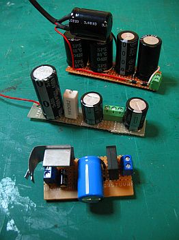
Okay, so much for the joys of theory. How does the actuality compare? The following supplies have now been prototyped and tested.
AVA101-1PSU Phase 1
Grant Wills claimed serial number 1 with his Lamington build, and demonstrated that the proposed voltage quadrupler is a practical and cheap HT supply.
A Phase 1 PSU, The Lamington power supply circuit.
This is the supply used for The Lamington and drives it to 15 watts output.
With 220uF's pumping 470uF's this follows the convention that if you have different value caps available you use the lower values in series and the higher values in shunt.
The HT decoupling network is also shown. The actual value of HT decoupling electros for the preamp and driver stages is unimportant as long as it is “enough”, and in cases where the off-load HT is 330V or less scrounged disposable camera flash caps will be ideal. All voltages are representative at idle.
Addendum: It is strongly suggested that builders fit a 150k bleeder resistor across each 470uF, and include a neon tell-tail within the supply (see AVA105, below).
Note: if you resort to connecting identical caps in series for increased voltage rating you must fit a bleeder across each cap to keep the voltages balanced. If you connect identical units in parallel for greater current you must fit a current-balancing resistor, around 47 ohms, in series with each. If you go series-parallel (say for your hex of KT88's) then you must fit both.
When I asked Grant about the supply voltage regulation he replied “about 5%, pretty much the same as the transformers themselves”. Very satisfactory. 310V out on idle.
- T1-2 = M2860, 30 volt (c.t.) at 500mA.
Note: the bigger M6672 at 1A and multiple useful taps is actually marginally cheaper.
- T3 = 2155-type as 12.6V centre-tapped at 1.2 amps. (note that this is center-tapped but not balanced to the 12AX7's - despite this hum is very low.
- C1-2 = 220uF/200V (see text)
- C3-4 = 470uF/200V (see text)
- all D's = 1N5408 (or any 600+ volt, 1+ amp diodes such as EM410, 1N4007, etc.)
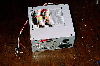
AVA101-2PSU Phase 1 - “The Flea”
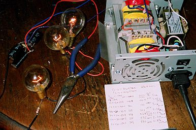
(l-r) flash-cap quadrupler, load lamps, AC from 2x 2A trannies
Update: 12/6/08
Test results for quadrupler built from scrounged disposable camera flash units, available Free! from your local film processor.
These flash units contain an electrolytic cap of between 80uF and 160uF, depending on the make, at 330 volts working, plus a high voltage diode.

 Caution! when disassembling the disposable cameras be sure to discharge the cap - some have been found with significant charge remaining days after the last use.
I wanted to see how this quadrupler would behave when fed with different AC voltages by tapping down on the trannies (both 2 amp units in this case).
Four diodes and two 80uF for C1 & 2, and two 120uF for C3 & 4 were recovered. A 220k/1W was recovered from a dead TV and used as the fixed bleeder across the output. The load consisted of three 40W globes in series with a 27 ohm resistor in the earthy end to measure the actual current (light globes are very non-linear as resistors, the current depending heavily on the temperature of the lamp filament).
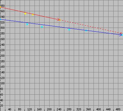
| Vac nominal | Vac actual | Vdco | Vdcl | @ Idc mA | Watts |
|---|
| 12+12 | 26.6 | 146.3 | 106.4 | 64.81 | 6.9 |
| 12+24 (or 17.5+17.5) | 40.1 | 221 | 182 | 80.00 | 14.6 |
| 12+30 | 46.7 | 259 | 221 | 87.41 | 19.3 |
| 24+24 | 53.7 | 296 | 258 | 94.07 | 24.3 |
| 24+30 (or 27.5+27.5) | 60.5 | 333 | 295 | 100.00 | 29.5 |
| 30+30 | 67 | 369 | 330 | 105.93 | 35.0 |
Vac nominal - voltage marked on tapping
Vac actual - actual voltage applied to multiplier
Vdco - DC output voltage, no load
Vdcl - DC output voltage, loaded
Idc mA - loaded output current
Watts - computed power output
The caps themselves got warm to the touch after a couple of hours at the highest power, so I would suggest a nominal output limit of 100mA continuous with recovered flash caps (but certainly parallel them if needed, or use larger ones from ratted computer PSU's, which we will come to, below).
While I used a mixture of tappings for these tests I suggest you stick to using the same tap on both trannies to balance loading. The actual tappings available are nominally 12, 17.5, 20, 24, 27.5 and 30 volts; so there are intermediate combinations not shown here.
Here is the main reason for using multi-tapped trannies - they allow tweeking of the HT supply voltage to “heat up” or “cool down” the output stage as desired or needed. In this respect this supply arrangement is much more flexable than more traditional supplies and allows variation of the HT alone without changing the heater voltage.
The trannies I used for these tests were the 2 amp version, much higher than required here, because they were to hand in the Phase 5 PSU (see below) intended to eventually drive a pair of 6L6's.
Whatever sort of valve build you are considering, a sample studio tonebox, a Watkins or Vox AC30 clone, or something much bigger, this quadrupler supply arrangement has shown it will deliver the goods and is very flexable and practical at minimal cost.
Where high voltage is required at low current, such as only a few milliamps for a stand-alone preamp, trem, or reverb, there are smaller 24Vac and 30Vac at 150mA trannies avaliable. The internal resistance of this supply is around 400 ohms and we must expect that these lighter transformers will produce a higher internal resistance and more sag under load, but for light loading this should be insignificant.
Again the reminder that even “small” power supplies like these are easily capable of delivering a lethal current. Sure 400 ohms is perhaps a hundred times higher than the mains, but it only takes a mere 10mA to kill and these supplies won't even notice if you happen to get connected across the output. The Earth Leakage Breaker or “Safety Switch” on your switchboard only protects you against direct connection with the mains and gives no protection at all the other side of a transformer.