A DIY low-cost toneful 15W guitar amp
that can be built with readily available “over the counter” parts,
by those with limited resources and skills.
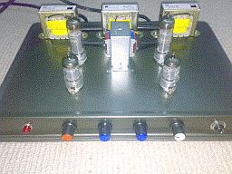
HT, Heater, HT;
6BQ5, Output, 6BQ5;
2x 12AX7's
all on a Lamington baking tray
|
http://www.ozvalveamps.org/ava100/ava101lamington.html | Created: 1/06/08 | Last update:
08:31 24/11/08
<<< OzValveAmps |
A DIY low-cost toneful 15W guitar amp
that can be built with readily available “over the counter” parts,
by those with limited resources and skills.
A major Thank You and pat on the back to Grant Wills for this very first AVA100-Series build. This build confirms the overall design, in particular the quadrupler HT supply, and the use of the simpler split-load Phase Inverter.
This joint co-operative design and development by
Grant Wills and Roly Roper
If you have specific questions about this build you can e-mail Grant at:
![]()
Update: 10/6/08
Contains:| Introduction, CAUTION, Design, Output Stage, Phase Splitter, Preamplifier, Power Supply, Construction, Bringing the amp up, Components, Conclusion, Notes, Parts List, Addendum |
This amplifier is designed for the person who has basic soldering skills and a healthy respect for high voltages who wants to build a basic 15W valve amp head for minimal cost and with a minimum of metalworking. It was designed and constructed to prove that you can build your own 15W amp using readily available “off the shelf” components here in Australia at low cost. (however, for the valves themselves, see Components - Valves, below -rr).
Depending on how adept you are at scrounging certain components to save costs, the maximum cost to build this amp will be less than $150. It was designed to be built without access to a workshop, and in fact the prototype was constructed on the dining table in my city apartment to prove that it could be built without special facilities or tools.
|
CAUTION!!!
It needs to be said that this amp generates potentially lethal voltages. It cannot be overstated that you need to exercise extreme caution when measuring voltages etc., on a working amp. NEVER hold the chassis with one hand while you are probing with the other hand. Put one hand in your pocket and probe with the other with the negative multimeter probe firmly clipped to the chassis earth point. Don't forget that even when the power is turned off, potentially lethal voltages may still exist in charged capacitors in the amp. Before working on or modifying the amp, wait for 5-10 mins to allow all capacitors to discharge. (Or better, use a clip-on lamp load to discharge the supply). The front panel neon tells you if there are still voltages present. Working on valve amps need not be dangerous if you apply due care, common sense and maintain a healthy respect for over +300V of high voltage. Note the suggested mods to the power supply to make it safer to work around. |
The design for this amp is conventional with the exception of the power supply, which uses some unorthodox techniques to develop the +300 volt high tension supply.
The design objective was to provide a 15W output which is typical for lower power “boutique” amps. This level of power is relatively easy to design with a broad range of output valves being suitable including 6BQ5/EL84, 6V6, 6GW8/ECL86, 14GW8/PCL86, 16A5, 6CW5, 6BW6, 6CH6 ... in fact pretty much any power valve with a maximum anode dissipation of around 10 watts.
The prototype used 6BQ5/EL84's as they are readily available, but any of the above valves would work fine.
Note: (10/6/08) Where the power meets the pentodes Grant made a number of changes to my original “mind-amp”.
The 6.3V lamp pilot light shown is deprecated in favor of a neon on the HT to provide a safety indication, and to save heater power.
- 6BQ5's for 6GW8's
- No bypass caps on preamp cathodes - apparently they were way too “hot” bypassed with excess stage gain to burn
- Top-coupling cap on Gain/Drive control
- Standard two-knob “James” tonestack

Referring to the circuit diagram of the amplifier, and looking at the bottom right of the diagram you can see the output stage. There are two power valves in the output stage in what is called a “push-pull” configuration. This allows the valves to provide the maximum power possible.
These two valves need to be driven in different directions (called “out of phase”) so that as one valve is driven harder, the other valve is turning off. You can see that each valve anode connects to each end of the output transformer primary winding with the +300V high voltage applied to the centre tap of the transformer. The secondary winding of the transformer drives the speaker.
In the long distant past, such an output transformer was readily available. However, these days these transformers have only been available by special order from overseas and have been very expensive. This amp however, uses a readily available and cheap transformer that is normally used as a “line transformer” for PA speakers.
Note: (10/6/08 - rr) Grant opted to use the M1115 line tranny, nominally rated as “15 watt”. My measurements suggest that these trannies are rated in “programme watts” rather than “RMS” or continuous watts. This means it will produce more transformer saturation grind, but I found that the smaller M1115 got excessively hot when driven to a continuous 15 watts by a pair of 6V6's.
I therefore suggest that intending builders seriously consider using the slightly larger M1120 “20 watt” 100-Volt Line tranny for amps intended to make more than 10 watts rms, or at least allow the space to fit a M1120 later if needed. Another reason for going with the M1120 is that it has 4, 8 and 16 ohm secondary taps allowing greater flexibility in speaker arrangements. While the smaller M1115 should be satisfactory for lead guitar and harp use, for other uses however like bass, keys, or even rhythm guitar, or if you are looking for a very clean sound such as semi-acoustic guitar use, the larger M1120 is recommended. The price difference is under $A10 and no circuit changes are required.
To the left of the two power output valves is a triode valve called a phase splitter. The purpose of this phase splitter is to provide out of phase signals to drive the two output valves. The phase splitter is configured so that the signals at its anode and cathode are out of phase with each other. These signals are applied to the grids of the two output valves to provide the “push-pull” drive required.
The benefit of the split-load PI form is that it only uses one triode section, but the penalty is that it has no voltage gain, so about 12Vrms of drive is required at the PI grid for full power output.
Located at the top of the circuit diagram is the preamplifier, or “front-end” of the amplifier. It is worth noting that each of the three stages or “valves” in the preamp is in fact one half of a 12AX7 dual triode valve.
The input signal from a guitar is applied to the grid of the first stage. At the anode of this first stage there will be an amplified version (gain) of the input signal. This is applied to the first volume control (marked the drive control) which together with the master volume allows the preamp to be set up for clean or distortion operation of the preamp.
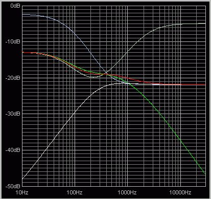
From the drive control, the signal is applied to the second stage. From the anode of this stage, the signal is applied to the frequency selective tone controls (sometimes called the “tonestack” or “EQ”) which provide bass and treble boost and cut using the typical “James” arrangement.
Controls min, mid, and max (1M tone pots)
Created using Tone Stack Calculator v1.3 from Duncan Amplification
Insertion loss about -20dB or 10:1The output of the tone control is applied to the grid of the third preamp stage which drives the master volume control.
The amp design is quite conventional, with the exception of the unorthodox output transformer, and has been used since the 1940's with a few different variations.
The power supply, however, is unconventional but very effective in it's role to provide the high voltage required for the valves. In the past, high voltage transformers suitable for a valve amp power supply were readily available, but are no longer available except by order at a high cost from overseas. Rather than use such an expensive, difficult to obtain high voltage transformer, we are using two cheap, readily available low voltage transformers to provide the high voltage.
Looking at the power supply circuit, you can see how this is done.
Addendum: (10/6/08) there are three changes to the circuit as shown.
- The fuse should be a 0.5A delay or “Slo-Blow” type,
- a 220k 0.5W bleeder resistor should be fitted across each of the two 470uF capacitors,
- and the pilot light should be a 240V neon type connected between ground and the +240V HT3 rail (with a suitable limiting resistor - e.g. NE2 neon (Jaycar SL-2690) with 270k resistor; or 240V Jaycar SL-2630, SL-2632 or similar).
Two inexpensive readily available 30 volt transformers have their secondary windings connected in series to provide a total voltage of 60 volts AC. This 60v is applied to a voltage quadrupler (alternatively called a charge pump) which multiplies the voltage to over +300 volts.
Just in case you think that we are getting something for nothing, the current that can be drawn from the 300V supply is only a quarter of the current available from the transformers combined 60V input. As the transformers are capable of 500ma of current, with the resulting output limit of (500/4 =) 125mA they can easily supply the 100ma of current required from the 300V supply.
The valves also need 6.3V for their heaters which is provided by a third low cost transformer.
A goal of this amp design was to keep the costs of construction to a minimum. In prototyping this amp, I was very mindful that most people constructing it will have limited metal working experience. In addition, commercial rack cases and cabinets can be rather costly.
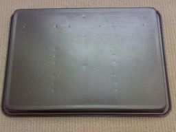
A solution to these challenges came in the form of a readily available, low cost ($5.99) lamington cake tin from Big W or K-Mart. An inverted cake tin provides an attractive, teflon coated chassis which is ideal for the amp.
The K-Mart at Northcote Plaza had the widest selection, the heaviest guage, and the cheapest baking trays so far found. New-fangled silicon rubber baking trays are not suitable for this construction.
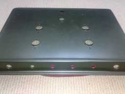
There are a number of holes to be drilled in the chassis, and reference to the layout diagram will allow you to mark out the chassis. I recommend that you mark out grid lines for the holes with a soft pencil. It really helps you see where you are going.
There are holes for the transformers, holes to pass the wires from the transformers under chassis, holes for the valve sockets, holes for the front panel controls pots and holes for the mains cable entry, fuse holder and mains switch.
It is highly recommended that you “centre-punch” each hole before you drill it. This will make sure that you drill the hole accurately without the drill bit wandering off target. You can centre-punch the hole with a proper centre-punch or use a large nail as a punch.
The drilling of the chassis assumes that you have or can borrow an electric drill with a range of drill bits up to 3/8 inch or 10mm. When you punch the chassis or drill a hole, always place a block of wood on the underside of the chassis. This will ensure that you do not damage the fairly light steel of the chassis.
There is a technique to drill the larger holes (up to 10mm) without the drill bit grabbing the chassis and bending it out of shape. Simply start drilling from a smaller pilot hole and then change drill bits to progressively larger bits to drill progressively larger holes.
If you find that your drill grabs the chassis a bit aggressively and bends the chassis, all you need to do is place your block of wood on the underside of the chassis, and gently tap over the top side of the hole with a hammer. This will flatten out the chassis fine.
Two holes drilled in the chassis need to be slightly larger than a 10mm drill bit. They are the holes for the fuse holder and for the mains switch. These need holes of approximately 11-12mm, and they can be made by either filing a 10mm hole out a bit wider if you have a small round file.
Alternatively, if you carefully angle a rotating 10mm drill bit at about 45 degrees to the chassis at several points in a circle with a rotating drill bit through the hole, the hole will be widened sufficiently for the fuse holder and mains switch. This requires care, and the chassis needs to be held fairly securely as the hole is opened up in this way. Initially, try a short burst of power to the drill to give yourself the confidence to do this.
The only holes that are too big to be directly drilled by the drill are the valve socket holes. However there is a solution to this, although it is a bit time consuming. This is accomplished by marking a circle representing the size of the socket hole on the chassis. Then carefully centre-punch and drill about 10-20 2mm holes in a circle just inside the marked circle. Then using a pair of side cutters, snip the chassis between the holes as close as you can to the marked circle. If you have a small file (often available from $2 shops) you can tidy up the final hole.
The way to guarantee that you end up with a tidy, correctly drilled chassis is to take it slowly, take it easy. You may want to practice your metal skills first on a flattened out tin can to get the feel of it. If the worst comes to the worst and you end up destroying the chassis, buy another one! At $5.99, you have just learned how not to do it!
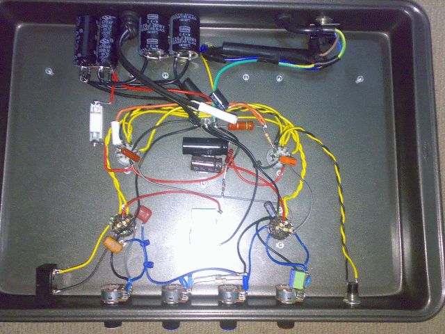
Construction of the amp begins by drilling all the holes. (It is desirable to do all the drilling you may ever need e.g. holes for a tremolo valve and footswitch socket, at this stage, and make sure the chassis is totally free of any metal turnings or grindings, before mounting any parts). Next, mount all the transformers using small nuts and bolts, and then mount the valve sockets and the rest of the hardware.
Begin by wiring the mains circuits (mains cable, switch and fuse). As you need to wire all three power transformer primaries in parallel (brown to brown, blue to blue), I suggest you simply wire them together and then tape and heatshrink the joints to be safe. I also recommend that you apply heatshrink to the fuse holder and mains switch for safety. Ratted appliances are a source of suitable mains-insulating items such as thick non-shrink sleeving held in place using cable ties.
In my prototype, I mounted the power supply capacitors by gluing them with contact adhesive to the chassis. Maybe a bit crude, but it works well and allows you to wire the power diodes directly to them. (or you can employ the many ties, and plastic and metal clips, P-hoops and clamps available)
You need to get the two secondary windings correctly phased so that the two 30V windings add to and not cancel each other - if the total across the series combination is 0V, simply reverse the connections to one of the windings.
I chose to construct the amp by using the valve holders as “tag points” and with a few exceptions, every connection could be made in this way. Where a logical “tag points” was not available, you can simply run a wire from the free component end to the corresponding point in the circuit and anchor the free end with a cable tie to an appropriate anchor point. (If you want a more classic look that is also a bit more robust than “aeroboard” you can mount a few tag-strips using the valveholder bolts, e.g. Altronics P2305, $0.55 ea - but don't use the grounded tag).
One very important aspect of construction is to use what is called a “star ground”. This simply means that a point is chosen in the chassis as a common earth point. Every component that connects to earth needs to be connected back to this common “star” point. Wiring the amp in this way will almost guarantee that you won't have hum or stability problems with this amp. (This implies the use of insulated sockets throughout, including input(s), speaker, line-out, footswitch &c).
To ensure you have the minimum problems with your amp, I suggest you take your time, and check, check and re-check the wiring of each component against the circuit both before you wire it in and after it is in place.
I also recommend that you measure the value of each resistor with a multimeter before you wire it into the circuit to make sure that you haven't mixed up resistor values.
Bringing the amp up
Addendum: 10/6/08 -rrPowering up a new build for the first time can be quite an adventure since the gear has never actually worked before and anything at all could be wrong. So it is best to initially bring it up in stages; starting with the mains wiring and trannies, then rectifier, HT wiring, and finally with valves for a signal test. In a more complex amp you would also first bring up the main amp from the master volume, then the plain preamp, effects preamp, and finally effects.
Check List (initial conditions; valves removed, 0.5A fuse fitted)
- Give the amp a good clean and shaking out to remove any loose wire offcuts, solder dags, lost screws, &c that might linger to cause a short.
- Check zero ohms from mains plug earth pin to chassis, others infinity
- Lift the 60Vac tranny connection to the multiplier/rectifier
- Wire Mains power via load-limiting lead with 15-40W globe
- Power up - DANGER! -
- Touch chassis with a neon screwdriver first, only then with back of your hand, feeling for any leakage “tingles” (meaning a mains ground problem to solve before anything else)
- Check 30Vac across each HT trannie, and 60Vac total (reverse one secondary if 2x 30V but no 60V sum)
- Check topside that 6.3Vac c.t. from heater tranny is appearing on the correct valve socket locations
- Unplug from the mains (don't just switch off - put the plug on the bench where you can see it, or in your pocket - and make it a habit)
- Reconnect 60Vac to multipier input, then isolate multiplier output (main HT feed) from rest of amp
- Attach meter to observe main HT voltage
- Power up - DANGER! -
- Check HT is around 375 volts
- Unplug mains
- Fully discharge the rectifier using lamp load (another worthwhile habit)
- Reconnect multiplier/rectifier output to amp HT rails
- Power up - DANGER! -
- Topside, check valve sockets for HT where (and only where) expected, anodes and screens (and -ve grid bias where fitted)
- Unplug mains
- Fully discharge the rectifier using lamp load
- Connect speaker or dummy load, set volume to 0 and tones to 12 O'clock
- Fit valves (in the right sockets!)
- Attach meter to observe main HT voltage
- Increase the load-limiting lamp to 100 watts
- Power up - DANGER! - be ready to quickly switch of if there are any signs of distress, sparking or frying noises, odd smells, or one of the valves starts to overheat. You should get an initial transformer bump before they settle to a quiet hum. Loud transformer hum suggests a short. The valves may crinkle on warming but quickly settle. There may be a slight warm valve smell as the valves burn any dust off, but there should be no smoke or acrid smells.
- Check the cathode bias voltage is correct
- Apply a signal (at this stage it is best to use a tape or CD track you know well) and gently advance the volume. Check tonestack for correct operation.
- Unplug mains
- Fully discharge the rectifier using lamp load
- Visual and touch-test whole amp for any signs of overheating, slow cooking, or other distress.
You should see over +300V available at the main HT supply with the amp idle. Other key voltage checks are approx +11V at the cathodes of the output valves and about half of the HT volts at the anode of each preamp triode. The phase splitter should have approx +80V at the cathode and +200V at the anode.
Finally connect a speaker and play to your heart's content!
If your amp does not work first time, don't panic!
In fact, this provides a great opportunity to learn about valve circuitry. If your amp does not seem to work, first check the main HT power supply voltages, then start at the output stage.
If all good here, simply continue to trace your way back along the signal path to the input socket, stage by stage.
- Is there approx +300V at each output valve anode?
- Is there approx +11V at the cathodes?
- If so, can you hear a click from your speaker when you touch each output grid with a (insulated handle) screwdriver?
For example if you have clicks when you touch the grid of the phase splitter, but not when you touch the grid of the last preamp triode, you know that there is a fault somewhere in the wiring between these two points. There is no need to completely rewire your amp.
These are called “blert” or “wet-finger” tests as they require no test gear at all apart from the amp itself. The classic first test is to turn the main volume up a bit and poke at the pot wiper with a screwdriver or even a finger. If you get a loud hum “blert” from the speakers the problem is in the signal path before there, if no response at all, then after there. Despite the instant simplicity, various wet-finger tests can be very valuable once you gain some experience and know what to expect. An insulated screwdriver produces a smaller more scratchy signal, but it's a whole lot safer than using your actual finger, which is “bad practice”.
Common things you find include; mistakes - wires or components going to the wrong place, such as mis-counting valve pins, mis-read value resistor colour codes or cap markings, or tranny lables; omissions or opens - missing components or the wire you were going to put in later and forgot or got distracted, points that should be connected but aren't; shorts - solder dags and free strands of hookup wire shorting points that shouldn't be connected (pre-tin all wire connections); blobby dry joints and poor soldering (simply re-solder with fresh solder and enough heat this time, and remove excess); screened lead outer that has melted and shorted to the inner due to excessively long soldering; faulty or broken components, particularly check all scrounged parts before using, but be aware of manufacturing defects - one of my trannies had two secondary tags almost touching. But most faults will be mistakes made by you during construction and you have to find and correct them.
Fortunately, this circuit is straightforward, and this kind of logical approach to faultfinding will allow you to locate the faulty wiring or wrong component.
General Components
And now, some comments on parts availability. All of the parts with the exception of the output valves are readily available from DSE, Jaycar and Altronics.
Be open to the possibility of scrounging resistors, capacitors from old TV sets, VCR's etc. If you can get your hands on such an old piece of gear, you will probably find most of the smaller electronics parts for your amp. Where possible, check any salvaged resistor for correct value before using it in your amp.
Valves
While 12AX7 valves are available from Jaycar, they are a bit pricey. My recommendation is to purchase your valves from Ebay. You can regularly see 6BQ5/EL84 valves for approx $30 a pair and 12AX7's for $10 from Australian sellers.
Alternatively, 6V6's are available for $30 a pair, and other Ebay traders sell more obscure types for the adventurous, such as 6CH6's for $4 each which work fine. Also, Rockby Electronics in Melbourne have at the time of writing 16A5 output valves for $3 each - they need 16V for their heaters, but otherwise will work ok in this amp - you may need to use a different transformer for the heaters depending on their heater voltage.
I highly recommend that you download data for your chosen valves from the Web - just do a Google search for data for your valve type. Read the data in detail - it will give you not only pinout data for your valve, but also a heap of further info that will help you understand valves better.
For further info on valves you can download an electronic version of any issue of the ARRL Amateur Radio Handbook, or the Radiotron Designer's Handbook. These are invaluable resources for the valve enthusiast.
Power Supply Capacitors
A 220uf 200V capacitor can be made by wiring two Jaycar RE-6210 (470uf 63V) in series (positive to negative). A 470uf 200V capacitor can be made up by wiring three Jaycar RE-6236 1000uf 63V capacitors in series (positive to negative, positive to negative). While these series strings of capacitors will work, they are not the best solution. A much cheaper (free!!) and better engineering solution is available however!
Do the rounds of your local computer repair shops, and ask for any faulty/dead computer power supplies that they may have lying around. These supplies each contain a couple of these 200V capacitors. Some later supplies only contain one 400V capacitor, but that could still be useable if you can find a similar supply with a similar value capacitor. These capacitors are ideal as they have very low internal resistance, and are designed for high current - they are ideal for your amp. These salvaged capacitors are what I used for the prototype and work really well.
Another source of suitable electrolytic capacitors for free! are used disposable cameras from your friendly local film processor. The caps in the various brand flash modules range from 80uF to 160uF at 330 volts working. These sometimes also contain (high-voltage) neons that can serve as high-voltage tell-tails.
Other Components
See the attached parts list which gives you information on where to get the relevant parts. Fortunately, there are several sources available for each component, so you should have no problems locating the parts that you need.
Parts are available from DSE (maybe), Jaycar and Altronics stores directly if you are near them, or alternatively, all of these suppliers (except DSE) provide excellent mail-order service by phone or the Web.
I hope you have as much fun as I did in building this amp. My prototype worked really well driving a 10” guitar speaker in an open backed cabinet. I will leave it to you as to how to finish your amp - you can build it into a combo style cabinet with a 10” or a 12” 8 ohm speaker, or build a timber shell for your amp and use it with an external speaker box of your choosing.
Either way, enjoy the sound of this classic 15W valve amp!!
All prices as at June 2008.
| Qty | Part, supplier |
|---|---|
| 2 | M2860 30V 0.5A (DSE $7.95ea, Altronics $9.40ea) Also suitable; (1Amp) DSE-M6672, Alt-M6672L, Jay-MM2008 ; (2Amp) DSE-M1991, Alt-M6674L, Jay-MM2005 |
| 1 | M2155 (DSE $9.95ea, Altronics $10.95, Jaycar MM2002 $10.95) Also suitable; (2Amp) DSE-M2156, Alt-M2156L, Jay-MM2004 |
| 1 | M1115 (Altronics $11.95) or M1120 (Alt- $18.95)(see text) |
| 2 | EL84/6BQ5 or other output valves (see text) |
| 2 | 12AX7 preamp valves (see text) |
| 1 | Chassis-Lamington Cake Tin (33x23cm) (Big W $5.98)(or K-Mart) |
| 4 | 2M Log Pots (DSE $0.51ea)(1M should also be suitable) |
| 4 | 20mm Push fit knob (DSE HK7705, HK7709/Jaycar P7040, P7042 $0.67ea)(must match pots used) |
| 1 | Input socket, insulated, switched (Jaycar PS0184 $2.55) |
| 1 | Mains switch (DSE P7668 $1.95/ Jaycar ST0570 $1.85) |
| 1 | Fuse holder (Jaycar SZ2028 $2.00) |
| 4 | 1N5408 (DSE, Jaycar $0.25ea) |
| 1 | Panel lamp (Jaycar SL2630 $1.20) |
| 4 | 470uf 63v (Jaycar RE6350 $1.28ea) OR salvaged from old computer P/S $0.00 |
| 6 | 1000uf 63v (Jaycar RE6236 $1.95ea) OR salvaged from old computer P/S $0.00 |
| 1 | 47uf 450V (Jaycar RE6125 $6.20) |
| 4 | 10uf 450v (Jaycar RE6078 $2.80ea) |
| 4 | 9-pin valve sockets (Jaycar PS2082 $4.40ea/Altronics P8500 with shield $5.00ea) |
| 1 | Packet rubber grommets (Jaycar HP0702 $3.40) |
| 1 | Mains cable with mains plug (salvage it from almost anywhere!) |
| 1 | Packet screws (Jaycar HP0400 $1.95) |
| 1 | Packet nuts (Jaycar HP0425 $2.05) |
| 6 | 100K 1W carbon film resistors (Jaycar RR2822 $1.05) |
| 3 | 470K 1W carbon film resistors (Jaycar RR2838 $0.70) |
| 2 | 10K 1W carbon film resistors (Jaycar RR2838 $0.70) |
| 2 | 1k 1W carbon film resistors (Jaycar RR2774 $0.35) |
| 2 | 2.2K 1W carbon film resistors (Jaycar RR2782 $0.35) |
| 1 | 1.5K 1W carbon film resistor (jaycar RR2778 $0.35) |
| 1 | 1M 1W carbon film resistor (Jaycar RR2846 $0.35) |
| 1 | 220K 1W carbon film resistor (Jaycar RR2830 $0.35) |
| 2 | 27K 1W carbon film resistors (Jaycar RR2808 $0.35) |
| 1 | 2.2K 5W wirewound resistor (Jaycar RR3306 $0.32) |
| 1 | 150ohm 1W wirewound resistor (Jaycar RR3278 $0.32) |
| 4 | 22nF 600V capacitors (Jaycar RG5232 $0.80ea) |
| 2 | 100nF 600V capacitors (Jaycar RG5236 $0.95ea) |
| 1 | 470uf 25V electrolytic capacitor (Jaycar RE6195 $0.65) |
| 2 | 1nF capacitor (Jaycar RG5010 $0.18) |
| 1 | 10nF capacitor (Jaycar RG5065 $0.18) |
| 1 | 100pF capacitor (Jaycar RC5324 $0.28) |
| 1 | 560pF capacitor (Jaycar RC5333 $0.28) |
Hookup wire (assorted colours) - free if salvaged from an old computer power supply
Altronics
Particularly: Output transformers, 15VA power tranny
http://www.altronics.com.auJaycar Electronics
http://www.jaycar.com.au
5/7/08 - It appears that the 6BM8 listed in thier catalogue as new in fact still hasn't even been ordered by their purchasing department at this stage.WES Components (Wagner Electronic Services)
Particularly: output tranny, “instrumental” speakers
http://www.wescomponents.com/Dick Smith Electronics (DSE)
http://www.dse.com.au
5/7/08 - Dick Smith Electronics is quitting components.Retrovox
David Crittle
Particularly: NOS valves
http://www.retrovox.com.auYour local “$2 shops” for sundries such as nuts and bolts, assorted sizes and colours of cable ties, light-duty tools such as screwdrivers and bit-sets with sundry drivers, fine straight and bent pliers, small sidecutters, Stanley-type “box-cutter” knives, jewler's sets with straight and Philips cross, Gaffer tape, sundry contact cement, superglue, and silicon sealant tubes ...
Jon-BP up in Cairns had some questions;
re: Component Values for AVA100-1
JBP> The cathode resistor on the 6BQ5 output valves is 150 ohms 5watt,is the cathode bypass capacitor 47uF or 470uF?
470uF. It's hard to go wrong making bypass caps larger.
JBP> On the cathode of the Phase Splitter pin 8, is this resistor a 2.2K ?
Yep, 2k2.
JBP> In the parts list they list 2 x 27K resistors,I can only see one in the power supply (voltage divider network to create HT3).
Is the 33K resistor that feeds the 100K plate resistors for the first 12AX7 supposed to be 27K or is there a misprint in parts list? They do not mention a 33K in parts list.
As a general rule, wherever you find a conflict between a circuit value and a parts list the value shown on the circuit should be assumed to be the correct one. In this case the value of this decoupling resistor is pretty arbitary and either value will do; in fact any value between about 10k and 47k should produce pretty much the same results, just a minor shift in the DC conditions of the first stage.
JBP> It mentions 2 MEG Log pots however shows 1MEG in circuit,which should I use?
Again, Grant's circuit shows 1 meg pots throughout. I can only guess at this stage why he mentioned 2 megs at all since they are rather harder to obtain; perhaps that's what he actually used out of his junk bin.
In theory using 2 megs for the gain controls should give a *very* slightly higher available stage gain as, in AC terms, these gain pots are effectively in parallel with the anode load resistor of the previous stage, so the choice is between 1 meg in parallel with 100k, or 2 megs and 100k.
Rt = 1/((1/100)+(1/1000))
	Rt = 90.9k

Rt = 1/((1/100)+(1/2000))
	Rt = 95.2k
... about a 5% difference or less than 1dB which is inaudable.
BUT the pots used in the tonestack should be 1 meg or they will tend to have their range bunched up at each end and not much change in the middle. Overall I would make them *all* 1 meg log for ease of ordering.
JBP> Can you recommend a suitable speaker?
This is very much a matter of individual taste, but whatever you choose the sensitivity (dB per watt) is fairly important in a low-power amp, so all other things being equal I'd go with the speaker that has the higher dB/W rating. I have used quite a number of Chi-1-di “instrumental” 12-inch units from WES components in Sydney as they are inexpensive and I've found them really good value for money. If you are looking for something more “classic” and “period” I'd ask David Crittle of Retrovox what he has currently in stock, but expect to pay a bit more.
Thank you for bringing these points to our attention and I will makes some changes to the page to try to clarify these points for others.
The circuit diagramme has now been enlarged.
|
|