


|
http://www.ozvalveamps.org/chandler.html | Created: 28/04/07 | Last update:
00:55 19/05/11
<<< OzValveAmps |
“Guitar City, Sydney”
incl. “Chandlers Pty Ltd, Brisbane”
The origins of these are still a mystery.
If you know anything about Chandler, or Guitar City in Sydney, please let us know.
| Combo, 40 watt head, PA Phono |
New: 19/5/11
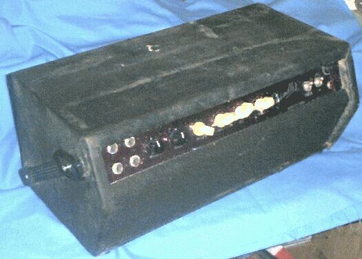
Andro Martinez sent pix of his newly aquired Chandler, with a curious backstory.
I just got my hands on this baby I thought I share it with you.
The owner said it belonged to his mother who played in well known Sydney scottish band she is 82 years old.
Anyway it needs a service, plugged her in and sounded good but some smoke came out so she's off now and going to the tech.
Hello Roly thought you may be interested in this.
Was in Guitar Crazy (Coogee NSW) for many years gathering dust. I traded a pedal for it. Speaker was blown so I replaced it with what you see now. Two el84's 0utput. It has a lot less headroom than my ac15. A great recording amp. I will get some shots of the internals to you soon. I'm pretty sure there was a shop called guitar city in Sydney? Early 80's. In any case I have never seen another except what is on your website. I don't believe the box is original. The vinyl looks like it is about 30yo. Hard to say. Just going off the colours used!
Cheers
Dino Shacallis

The two black controls are tremolo Intensity and Speed.


It looks like a pair of 6GW8's so it will be about 10-15 watts output.
The case is quite large for this class of amp and that should tend to make it more “full voiced” where smaller cabs tend to reedy or even shrill.
I found this one as a chassis and case in the explosives store behind an old sawmill. The only difficulty was the very large python wrapped around it.
The valves were gone but the remainder looked valuable if not intact. The very lumpy transformers and white chicken-head knobs made it instantly interesting even covered by years of grot. The python's interest was because some native mice had filled it with straw and set up house inside.
The more I cleaned it up, the better it looked. The Henderson power tranny checked out okay, then the A&R 2653 60W output tranny too. When all the HT caps reformed okay using the Megger the prospects of bringing it back to life started to look really bright.
I traced and drew out the circuit, at the same time testing every component from input to output using an ohmmeter or Megger. This identified a number of failed components which were duly replaced. These are marked (*) in pencil on the circuits.
It took a bit of detective work to figure out what the original valve line-up had been, but after checking base wiring and output transformer impedance it resolved to all twin triodes to EL34/6CA7's.
No surprises here (unless you happened to touch the uninsulated can of one of the electros in the HT voltage doubler! - naughty, naughty). A very conventional arrangement including passive Baxandall tone controls. Tremolo cathode coupled to an early preamp stage. Two EL34/6CA7's in cathode bias.
View preamp circuit (200kb jpg).
View main amp and power supply circuit (250kb jpg).
One curiosity is the use of cathode bias on the 6CA7 output pair. This alone seems to limit the output power to around 40 watts, while the valves, power supply and output transformer all seem capable of 50-55 watts. The power transformer in particular is very generous with an estimated 230 watt core. So a conversion to fixed bias may be in its future.
Other curious items include a HT triple electrolytic with only two sections connected; the output transformer having a ground on its tap rather than common; only a fuse between active and the power transformer; the standby switch only switches the preamp HT.
The phase inverter is a split-load type, but it uses an uncommon form of biasing called contact bias. Using cathode bias the highest allowed grid resistor is 1M ohm, but the 12AX7 data allows this resistor to be up to 10M ohm to develop contact bias. This bias is due to the tiny current that flows out of the grid through this resistor. Another way of looking at it is that the grid collects electrons, negative charge, which tend to repel other electrons (bias) and leak away via the 10M, maintaining an equlibrium.
While this saves a resistor and works when new it is particularly suseptable to bias upset by leakage through the input coupling capacitor from the anode of the preceeding stage. Also to age instability in the 10M resistor.
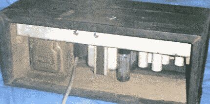
HT filter choke left front; live electro in black; original speaker connector front center; RCA tremolo footswitch connector front right; valve cans scrounged from an old VHF TV transmitter.
Four input sockets, two for straight, two for tremolo channel. These are the same sensitivity in each channel, but the straight channel has about three times more gain.
Controls are:
Intensity; Speed; Vol1,2; Vol3,4; Bass; Treble; Standby; Power; Pilot.
Back panel: (retro-fit 6.5mm sockets) 8 ohm speaker, 0dBV line output.
The ply case clearly isn't the original. The chassis is now secured by screws through the end plates, but in the view above two of four holes through the chassis show where it was originally hung, Fender-style, from the top of a different case.
The case front plate was missing, and remaking another one revealed the existing case is a nice one-off owner built effort.
The cloth covering I used is worth mention. These days cases are often covered with carpet. This is in fact boat carpet and priced accordingly at $15-$25 a square metre.
The local plant nursery stocks “root balling cloth” (don't ask, it's Secret Horticulturists Business ;), a black synthetic fabric so tough I literally have to use tin-shears to cut it. It comes 2m wide and costs around $2 a running metre, or a buck a square. Four years on the road on various bins and it still looks great.
The original speaker connector and its awkward position is a strong clue. This type were commonly used to connect to the speakers below in a combo unit, and from just this position on the chassis. The rear 6.5mm jack sockets are a retro-fit, so it looks like it has been de-Combo-ised at some point.
But at this power output level and vintage it is unlikely to have had only one speaker in the cabinet yet it would have been no wider than the 18 inch chassis.
So this is an “artists impression” (guess) what it might have originally looked like.
A little under three feet, or one metre, high.
Covered-up power wiring, and strapped down filter caps, but otherwise pretty much original.
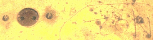
Detail showing the old style small-pin/large-pin speaker socket, and the chassis marking in pencil “No2”. The matching plugs were just an insulating disk with two pins, very minimal.
It is not uncommon for a manufacturer of a product like guitar amps to make a special batch for a particular customer to their requirements, even if that is only a front panel with their name on it - “badge engineering” it's called - the only bit they engineer is the badge. Tandy's “Realistic” brand is a classic example with many of “their” products being made by others and bought-in.
So the “Guitar City” front panel logo strongly suggests that this is one of a batch made for a music shop, perhaps Chandler their own brand, and that this is number two of a short run of perhaps ten or a dozen such combos.
But it doesn't look like a backyarder job, the chassis metalwork is properly done, even the flimsy light purple anodised front panel, so my hunch is that it was built by an existing amp builder like Moody, and badge engineered for Guitar City.
New: 23/10/09
“Chandlers Pty Ltd, Brisbane”
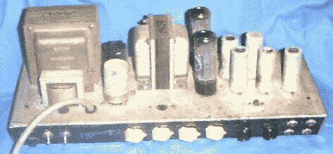
This is typical of the sort of equipment that was used as a small hall PA prior to the advent of television in Australia. The strong clue is in the twin 12-inch speaker boxes with long leads, allowing them to be placed either side of the stage.
Apart from straight PA for meetings this would have been pressed into service for vocalists with a small (accoustic) dance band, and even as a “disco” for small dances. It's also the sort of gear that might have been pressed into service to provide sound for film screenings (although later projectors came with internal amps and often with very similar split speakers).
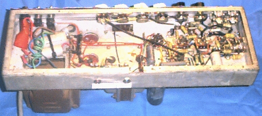
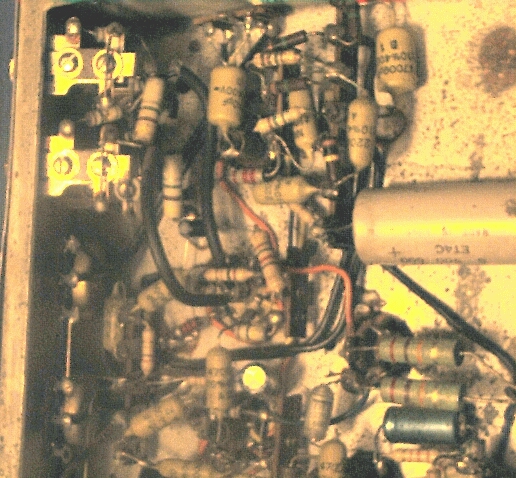
From the pix we appear to have a couple of rectifiers, 6V6 push-pull output, driven by 6SJ7 pentodes. Note that the input pentode is on a floating shock-mounting base.
Another feature is the ability to run from a car battery, also found in many AWA PA's of the era. The can at rear-left is a vibrator, basicallly a fancy buzzer, arranged to switch incoming 12 (or 6) volts into a winding on the mains tranny.
“Switching” between mains and battery operation was inherent to the lead used, each with a mutli-pole socket on the amp end connected and jumpered as required. Because vibrator supplies had sparking contacts that generated a lot of hash it is more normal to see a vibrator base surrounded by large waxed-paper caps.
Click on proofsheet to download all images in a zipfile (2Mb).
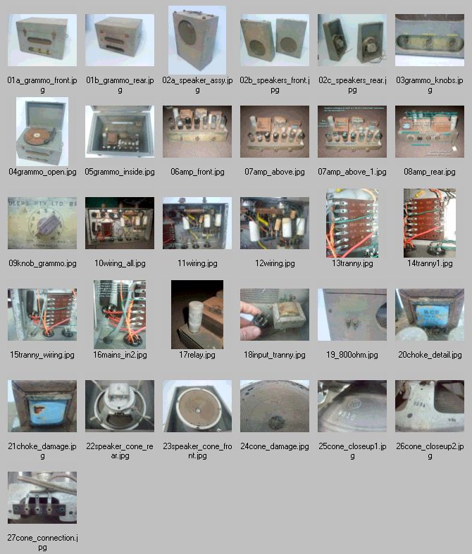
Source: Muzza
|
<<< OzValveAmps |
