|
http://www.ozvalveamps.org/choking.html | Created: 31/12/10 | Last update:
03:50 30/06/11
<<< OzValveAmps |
Output stage choking under extreme overdrive.
New: 31/12/10
There is a strange thing that can happen when a guitar amp is really seriously over-driven, a sudden sagging in power just when you need it most - the amplifier “chokes”.
This should not be confused with power supply “sag” which produces a similar but much milder power flattening. Choking is much more severe power dip like the volume being turned right down for a few (critical) moments.
The effect is a bit like a compressor gone out of control and overdoing it. If the guitarist lays off the drive for a few moments the amp will recover, but it will happen again on strong drive.
You won't read about this is on Hyper-Fi sites; they never operate their output stages anywhere near the extreme conditions of a guitar amplifier.
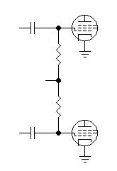
Here is the section of a grid-biassed push-pull output stage under consideration;
Drive is entering on the left from the phase-inverter. The grid resistors are going off to the bias supply.
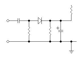
And here is the input circuit of one side of it. This shows the development from conventional half-wave rectifier (left), the same components simply re-arranged to similar effect (centre), and finally (right) replacing the diode with the grid-cathode of the output valve(s). This illustrates how the grid-cathode diode of the valve and the coupling cap form a negative half-wave rectifier (for signals greater than the bias), with the grid bias feed resistor as the load. Rectified overdrive voltage is added to the bias voltage.
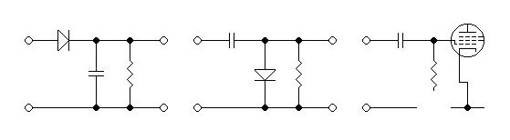
Assuming a grid bias of -32 volts, then for incoming signals up to 32 volts peak the output valve grid effectively looks like an open circuit - the grid-cathode diode remains reverse biassed.
Under no signal conditions the incoming coupling cap is charged to the voltage from the PI (let us assume the anode at 200 volts, and the grid bias supply at -32 volts, a total of 232 volts.
Now we cause the PI to drive the output stage with a lot more than 32 volts peak, perhaps 50 volts peak.
For signal voltages greater than 32Vpk the output valve grid circuit now looks more like the circuit in the middle. The grid/cathode circuit is now a forward-biassed diode and charge will flow, and because of its direction the grid circuit will tend to get more negative.
This excess charge gets stored on the coupling cap (232+18=250), and is only bled away via the grid resistor and bias supply, giving the recovery time constant.
Because the grid bias resistor is normally a fairly large value, say 100k to 470k, the time constant with the incoming coupling cap is significant. And because bleed value or load is so high the amount of excess bias will be equal to the peak voltage of the overdrive, in this case -18 volts extra. On top of -32 volts of normal Class-AB1 bias a total of -50 volts of bias will shut any output stage down.
This one has been doing the rounds for quite a while now; it basically says that the drive impedance, the PI loads, should be reduced to flog it into submission with grunt. Reducing the load resistors in the PI is often suggested, and this will certainly lower the drive impedance.
But once we understand the actual source of the problem (above) it is easy to understand that anything done to simply lower the drive impedance and drive the recification harder will only enhance charging of the coupling cap.
All such “answers” are simply wrong because they mis-understand the cause of the problem and may be a bit of creep, uncritical adoption, from the Hi-Fi world where lowering drive impedance can help some issues - but only in their linear turf below overdrive/clipping.
Other suggestions, such as lowering the coupling cap and grid resistor values to shorten the recovery time constant may certainly help, but they don't address the basic cause.
Most output stages will happily tolerate their grid resistors being reduced, but there will be some loss of level from the PI because its AC load is thereby also reduced. {This could also be seen as a backdoor case of “Turn Down!”, below} The coupling caps can also be minimised for the service, both of these reducing the time constant of the effect but not removing it. If we are considering a bass amp these are not particularly attractive options.
This is where a resistor is introduced into the output valve grid circuit right at the grid. The effect of this is to limit the charging current available during overdrive.
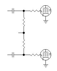
Again not a full cure, but it at least addresses the reality of what is going on during overdrive, and in some cases may be sufficient.
Many amps already have such a stopper fitted to prevent radio frequency instability, typically between 1k and 5k6. They are a good idea with all power valves. If choking is a problem these could be increased to reduce charging, but care has to be taken not to go higher than the output valve can tolerate (since large values introduce bias errors).
Well, ... yeah. But we don't all play moody Jazz. Certainly a split load phase inverter is less likely to cause this sort of trouble because of its limited swing, and swing-limiting zeners and clamp diodes have also been suggested.
These measures will work, but you may as well save the trouble and just turn down.
And that's hardly likely to satisfy the Thrash Metal crowd.
The answer as I see it is to start with a driver that won't choke no matter how hard you hammer the snot out of it.
This proposal is to use DC-coupled cathode followers between the phase inverter and the output grids. Properly biassed this would provide the bias feed and coupling capacitor-less drive to the grids.
Naturally this means an extra twin-triode stage, and the potential complexity of DC interstage coupling. There are some potentially serious implications here of heater failures and the like, but unlike the “answers” above this arrangement should certainly solve the problem and deliver hard no-choke drive.
The fact is, while you stay with capacitive-coupled input this is always going to occur, so I'm tossing this one in because it seems to have been overlooked.
As the cathode-follower shows, one way to avoid caps charging up is not to have any, but it can also be done without adding a valve (and its heater load).
If we dig back into very early amplifier circuits we find that transformers were once widely used for audio interstage coupling, partly because of the unavailability of suitable capacitors. It was also common with higher power output stages to use transformer-coupled power drive to Class-B finals.
In many respects transformer coupling is inferior to capacitive coupling; cost, weight, prone to magnetic noise, drive difficulties. On the plus side it can inherently phase-invert (center tap), and it presents a very low resistance path between the bias supply and the grids.
Applying negative feedback around two transformers might be problematic, but many guitarists seem to favor amps with no NFB, and in any case it isn't impossible.
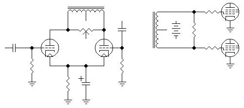
On the right, the output side. The secondary is centre-tapped. The ends are connected to the output valve grids and the centre-tap is connected to the bias supply. As far as DC goes the grids are now directly connected to the bias supply.
On the left is one of many possible drive arrangements. A driver transformer with a gapped core suitable for Class-A drive is a rare beast, but there are quite a few signal isolation transformers cheaply available with a centre tap on both primary and secondary, so a push-pull driver is possible. A prime consideration in selection is sufficient insulation and voltage withstand between primary and secondary since the primary will be operating at HT and the secondary near ground.
A Para-phase or unity-gain inverter PI is implied here, but a Long Tailed Pair with NFB returning on the right hand side is also possible.
In a transformer-coupled Class-AB2 or B2 amp the driver is required to deliver actual power, current as well as voltage, because it is expected to maintain drive into grid current.
In the case of a Class-AB1 amp we don't want drive to continue into significant grid current, so the driver stage can be a limited voltage amplifier that is simply clamped by the grids going positive.
During this exploration I began to wonder why choking seemed to be a problem associated with fixed bias output stages, but apparently not in cathode biassed amps.
Was this simply a matter of power levels, or is there something about cathode bias that makes choking less likely?
When we get one volt of overdrive with fixed bias this simply adds to the fixed bias supply. The reduction in output stage current makes no change in the bias voltage.
When we have the same overdrive in a cathode biassed output stage the current tends to be reduced, but as it reduces through the cathode bias resistor so the bias generated also falls somewhat, tending to absorb the overdrive bias and compensate for it, at least for moderate overdrive.
The bias resistor also provides some small inhibition to overdrive charging currents, unlike the grounded cathodes of the fixed bias case.
|
|