Well they require heater(*1) power to do that, and that has to be run all over the chassis to every valve.
Almost without exception this is 6.3 volts AC from a specific winding on the power transformer.
Twin triodes such as the 12AX7 have a center-tapped heater rated at 12.6 volts AC but are normally operated with the heater sections wired in parallel on 6.3 volts AC (*2).
If your chassis has a valve rectifier then it will likely have at least two heater windings, with one reserved for the rectifier alone.

Warning!
The rectifier heater circuit may well be at full HT voltage.
If the rectifier is a directly heated type this circuit WILL be at full HT.
Also, if it a directly heated type this winding will almost certainly be 5.0 volts AC. Connecting a 5 volt rectifier to 6.3 volts will result in a very short rectifier life, if nothing else.
Heater wiring must be sufficiently heavy to carry the currents required, about 300mA per preamp valve and 900mA each for power valves, which quickly adds up to 3 or 4 amps (but check the data, some valves are real hogs).
Voltage drops in the wiring are important as the graph below shows and the voltage at the valve pins must be well within 5% of the rated value. The rule of thumb which also applies to light globes is “five percent up or down halves or doubles life”.
The emission of a thoriated-tungsten cathode however actually falls off again with increasing temperature and they are designed to be operated at a peak point between 1950 and 2000°K.
Most heater wiring was originally done in 10/010 - 10 strands each of 0.010 inch - heavy hookup wire with thin low voltage insulation.
7/.0076 inch = 7x0.2 mm, 0.28 sqmm, 2.8 Amp, light hookup
14/.0076 inch = 14x0.2 mm, 0.44 sqmm, 4.4 Amp, med hookup
10/.010 inch = 10x0.25 mm, 0.49 sqmm, 4.9 Amp, heavy hookup
23/.0076 inch = 24x0.2 mm, 0.75 sqmm, 7.5 Amp, mains
Because the heater circuit is AC and at a fair current it has a considerable 50Hz magnetic field around it.
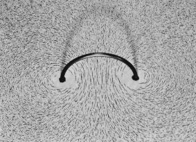
This field will induce hum in any nearby signal loops.
It makes sense to run two or three heater circuits from the tranny to the output valves, middle section, and front end, to minimise individual loop currents. Wiring should run from less sensitive stages towards more sensitive stages, with the critical front-end pre's at the end of the run where the current is least.
All the heater wiring should be tightly and uniformly twisted at about 2 twist/inch (1/cm) to cancel out most of the radiated field.
The tranny lead-outs are too fragile to be tightly twisted but can be given a gentle twist of half to one turn per inch depending on the wire gauge, concentrating on keeping it even rather than tight. Don't strain the wires where they enter the transformer; they are boofy components but the windings are actually quite fragile. This short run to the distribution tagstrip is normally a long way from the preamp and not an issue.
To make uniformly twisted heater wire,- take a length of white (with a black stripe if you've got it), say about four times the run you will need.
- fold it in half so it's doubled
- catch the ends in your bench vyce (or your drummer and a pair of pliers)
- catch the loop in the chuck of a hand or cordless drill
- while firmly pulling tight, wind/press trigger
- take it up to about 2 turn/inch (1/cm) but don't overdo it or you'll break strands inside
When installing, hold the free end with pliers and lever against them with your side-cutters to strip the insulation. That way you don't disturb the evenness of the twist which is important to best cancel the field.
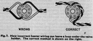
Wrong
This is the wrong way to wire heaters at a valve.
By going around each side, a single-turn loop is formed right under the valve where there is little metal in the socket to impede the magnetic field from the open loop reaching up and modulating the electrons in the valve above.
Right

This is the right way.
The loop is folded back on itself, tending to cancel its field, and what there is will now be over the chassis.
It should be routed down against the chassis, and along chassis corners, but it must be kept apart from sensitive signal wiring.
Where heater wiring must cross signal leads it should do so at right-angles and never run close in parallel.
Here is another way of making sure the heater feed is maximally twisted, although I'd run it around the left side of the typical power bottle, pins 2 and 7, to keep it away from the sensitive control grid, pin 5.
Source: Technical Topics, Pat Hawker
With the commonly used twin-triode preamp the heater is actually 12.6 volt with a centre-tap, and is normally used with the two section heaters in parallel on 6.3 volts. This means that pins 4 and 5 are tied together and fed from one side, while the other side goes to pin 9, so the layout above right is suggested. (Triode data)