
From EF86 data sheet
|
http://www.ozvalveamps.org/microphonics.html | Created: 09/11/09 | Last update:
18:45 08/12/09
<<< OzValveAmps |
by Tim.
Some of us will never come across microphonics, and others have a long recollection of problems and solutions. Maybe you've just experienced microphonics for the first time - well read on.
| Tim wrote with an excellent summary of his experience with a microphony problem, his related research into microphonics in valves, in particular the EF86, and his cure for the problem. I felt that there would be wider interest in his findings than just a neat hack, and asked him to expand his summary into a full article, and this is the result. -rr |
New: 16/11/09
When parts of the structure in a valve vibrate, new signals can be generated and amplified. A guitar combo is an excellent way for the new signals to be amplified and then fed back into the microphonic valve by speaker vibrations, with the result usually being a resonant howl or squeal similar to feedback when you place the stage microphone in front of the PA speaker.
Microphonics also relates to anything in your rig that can vibrate and cause added signals - parts such as pot wipers and oxidised pins in sockets are known to have caused problems. (an example)
A quick check of the forums, or books, typically directs you to swap tubes, or give up on using a certain type of valve. This is good advice and you can often do a quick fix and get back to other more important things, but microphonics is an interesting issue and you can explore further.
The valve most prone to microphonics is a high gain type positioned at the input of an audio amplifier. Microphonics became problematic in early radios, phonograms, and guitar amplifier/speaker combos. In those early guitar combo days of the 1950’s, the very high gain EF86 used by Vox (AC-15, AC-30) became notorious for microphonics. The ubiquitous 12AX7 can also cause microphonic headaches, but most of us will never experience it. (see Addenda)
In the early days, valve manufacturers and equipment designers grappled with microphonics as best they could, and the effect even had its own official definition “The periodic voltage output of a tube produced by mechanical resonance of its elements as a result of sustaining mechanical excitation”! Some manufacturers even specified microphonic performance in datasheets.
Mullard’s investigation into microphonics, published in 1962 [Ref 1], has provided the most enlightening set of experimental results to help characterise the microphonic signals that can be generated in a vibrating valve.
Vibration of a valve, like the vibration of a speaker cone, involves movement backwards and forwards in a certain direction, although unlike a valve, a speaker cone is restricted to movement in just one direction only - unless you really crank it to 11!
Vibration, and its effects, are scientifically characterised by the term acceleration, and the direction of that acceleration. To relate to acceleration, think of turning up the amplifier volume and watching the bass speaker cone move more - the cone experiences a higher acceleration level and the sound is louder.
In the speaker example, the cone has to accelerate at a higher level to reach a greater deflection distance - another analogy is to imagine a car at the grid starting line - it accelerates for 1 second, and reaches a certain distance from the line - if it had accelerated harder it would have gone further in one second.
So a valve that experiences a higher level of vibration is, in a scientific sense, experiencing a higher level of acceleration, and hence a higher level of deflection distance of internal parts.
Understanding the vibration term of acceleration is a big help when looking at the Mullard experimental graphs.
The first graph presented in [Ref 1] shows the different levels of acceleration experienced by a valve in a test radio receiver, as a function of frequency.
It’s like shaking the valve at a 20Hz frequency and seeing how large the vibration is within the valve, and then comparing results for measurement taken from shaking at higher frequencies all the way through to 20kHz. From the graph we see that the valve’s guts can reach relatively high levels of acceleration at some specific frequencies - sort of like how my son’s old Ford Falcon vibrates noticeably at about 75kph!
Of the many parts that make up a valve, the part of the valve that typically gets the blame for microphony is the wire forming the grid-1 structure (the typical input control grid), as the anode and cathode are more securely fixed and the other grids, if any, have much less influence.
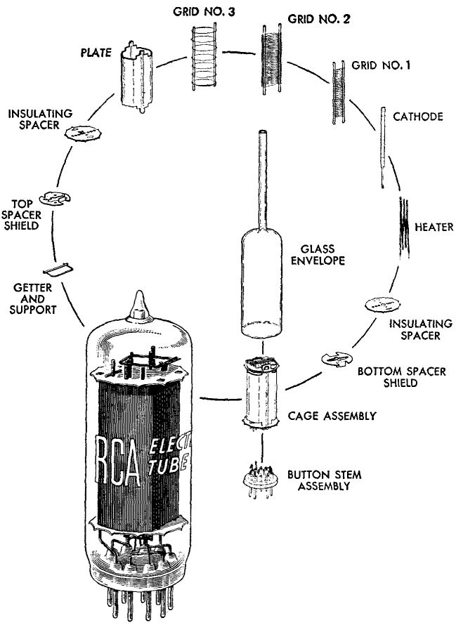
A typical grid structure is an elliptical helix held between two vertical support wires. These form half-ellipse “leaves” which vibrate freely when excited at the right frequency. The mechanical structures in a valve have very little dampening, as they are in a hard vacuum, and the metal supports are rigid. Valve designers make the supports as rigid as possibly to reduce the physical deflection of parts, and to push the resonant frequencies of parts as high as possible.
Pre-historic valves were made with the guts (cathode, grid and anode parts) standing up in the middle of a glass bulb, like the filament in an incandescent light bulb. You shake the light bulb, and the filament noticeably vibrates, sort of like a tuning fork.
The valves in common use have the cathode, grid, and anode parts pinned between two transparent mica disc, and the mica disks are squeezed into the cylindrical section of the valve’s glass envelope during manufacture.
Some preamp valves such as the EF86 only have one mica disc located towards to the top end, with the base of the valve providing the other point of clamping. Clamping the parts and supports in more than one place reduces the deflection that occurs for a given acceleration of the whole valve, just like plucking a guitar string with a finger on the 20th fret position compared to an open string.
[Ref 2] illustrates some techniques to determine which part of the valve structure is generating microphonic signals, and in which frequency band. But unfortunately doesn’t elaborate on how the tested valve was mounted, or the acceleration level experienced, so we can’t glean much else.
It is the physical deflection of parts, relative to other parts that generates a microphonic signal. For example, when the spacing between the grid-1 turns vary, the valve transfer function (gm - Mutual Conductance, or “gain”) changes.
Manufacturers had a simple test to detect 'vibrant' valves which involved 'clanging' a valve with a striker, as shown in the picture.
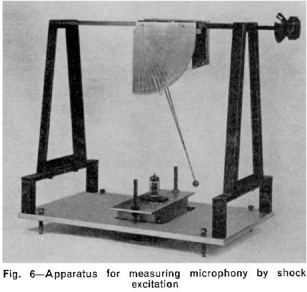
All the parts in the valve are shocked into vibration simultaneously, and with the valve operating in an amplifier the test was how loud the amplifier output became. It was a crude comparative test at the time that could have benefited from some modern spectrum analyser technology. But they made the test look scientific, and introduced the meritorious term of “signal-to-clang ratio”, which no doubt was abbreviated to SCR in dB.
Another characteristic of the clang is how quickly it dies away - which refers to the damping, or resonant Q, of the parts that vibrate. More modern techniques such as “waterfall” plots, which are commonly used in loudspeaker driver specifications, would be an excellent way to appreciate the decay in “clang” with time.
Going back to the Mullard reports, the second graph in [Ref 1] shows the signal level generated in a valve when shaken at a range of audio frequencies. The same level of shaking (acceleration) is used, and the result is that one frequency (about 2.8kHz) is up to 25dB louder than other frequencies - that’s quite a large turn on the old volume control!
Similar to [Ref 2], the Mullard reports has photographs and test results for changes made to various structural parts, but is more enlightening as it compares signal levels generated.
However it is the third graph shown in [Ref 1] that is most significant, as it provides a basic understanding for how we should practically manage microphonics. The third graph indicates that for a population of the same valve, from the same maker and manufacturing batch, the relative level of microphonic signal can change over a 10-to-1 ratio, which is 20dB. This is the base reason for the advice to “swap valves until you get a good one”.
However this generic advice to swap valves comes with some major provisos. Firstly, you may not know if you have a bad, mediocre, or good valve to start with - so buying in more valves may become expensive.
For the same valve type there can certainly be structural differences between valves made by different manufacturers, and even by the same manufacturer over time. And yes some manufacturers, and some vintages of a certain valve may well have across-the-board lower microphonic levels - but take all this with a grain of salt, as within each manufactured batch you are still likely to get a large variation.
Secondly, even if you do swap to a better valve, it is still likely to be generating significant microphonic signals - sort of like the rocks in the river being visible or being just under the level of the water. This point moves the discussion into “valve sound” and perceptions, as we start to talk about the “quality” of extra sounds added to the original signal by the audio chain (eg. in guitar parlance the type of guitar, string, pickup, lead, preamp valve, coupling capacitors, phase inverter topology, output stage bias level, output transformer manufacturer, speaker, level of overdrive, tone setting, the list goes on . . . ).
Thirdly, many people have experienced valves that become more microphonic with time. This is a sobering point when you lay it over the first and second points. Physically, this point make sense, as the physical expansions and contractions and aging of metals are highly likely to change the tight grip of the mica disks to the valve guts, and to the glass envelope over time.
This apparent “loosening” of a valves innards may go some way to understanding why a fresh batch of valves from the same manufacturer can measure such large differences in microphonic levels.
Apart from the choice of valve, the other countermeasure to alleviate microphonics is to reduce the level of vibration experienced by the valve. This is where human ingenuity has really made its mark! Man, do we have a wide variety of solutions to throw at this problem.
The obvious solution is to physically separate the amplifier from the source of vibration. In a hi-fi context this usually means placing the amplifier on a humungous concrete bench some distance from any speaker. Oh, and possibly putting a nice Perspex fence around the shiny valves to reduce the sound waves directly hitting the valves.
At the other end of the rainbow sits the guitar rig, with the head unit sitting on a quad box, or worse still a combo with two 12” speakers positioned just a few inches from your 12AX7 or EF86.
Firstly we should try to decouple the head unit, or the amplifier chassis from the speaker box. Any form of relatively soft, compliant interface is a good start (eg. foam rubber). For a head unit this could be as simple as replacing old hardened rubber feet (or lack thereof), or inserting old mouse mat under the base. More exotic means could be tracking down blocks of Sorbothane, or investigating how hi-fi’ers isolated their turntables in the days of 12” LPs. Ingenuity to the fore!
Technically, if a head unit was sitting on a cab with a spring in between (imagine a block of foam rubber as the spring), then if the head was pushed to one side it should vibrate back to a neutral position at a natural frequency well below 50Hz, as the spring only attenuates vibration at frequencies sufficiently above the natural resonance frequency of the head on the spring.
Datasheets for commercial isolator pads include “load versus natural frequency curves” which allow a simple way of choosing a suitable pad when you know the weight of your head unit.
A simple but less easy method to measure the natural frequency (Fn in Hz) is to;
Then calculate;
- measure the mass of the head (m1 in kg),
- then add (or subtract) an extra mass (m2 in kg) to the head,
- and measure the vertical distance (d in meter) moved by the head.
Fn = 1/(2 π) x sqrt(k/m1)where;stiffness k = m2 x g / d
g is gravity (9.8 m/s).For example, adding 5kg to a 15kg head unit compressed the block of foam padding by a distance 5mm (0.005 meter), so
k = 5 x 9.8 / .005 = 9800 Nm,and henceFn = 0.16 x sqrt(9800 / 15) = 4Hz. . . and so this foam padding would attenuate vibrating frequencies above about 10-20Hz.Secondly, we should try to decouple the valve from the amplifier chassis. A common vintage method was to use an isolated valve base which had an internal rubber bushing that went hard over time. A more exotic means was to spring mount a section of the chassis such as used in the STC 100W amp chassis.
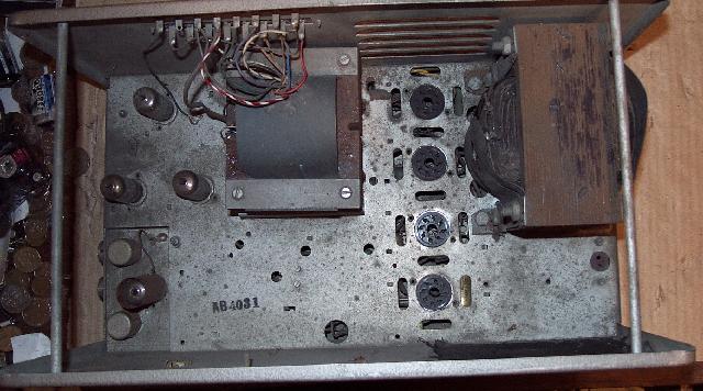
Floating preamp sub-chassis, lower leftMore modern products include valve interface adaptors, such as [Allnic Absorb-GEL] and [Ref 3]. A simple homemade alternative is to “float” the valve base with about 1mm of pliant sealant as the interface.
You may be lucky enough to do this without having to remove or replace the valve socket - eg. loosen the valve base retaining bolts (or rivets) and push the base clear of the chassis about 1-2mm and apply a flexible sealant into the gap (eg. Selleys All Clear universal co-polymer sealant) and then semi-tighten the nuts/bolts. However the valve is very lightweight and may well have a high natural frequency if the sealant is too stiff, and so adding some mass to the valve may be necessary to get any significant benefit.
Lastly, we can attempt to reduce any tendency for the glass envelope of the valve to resonate, and to stiffen the glass as an integral structural part of the valve assembly. The technical reports cited don’t discuss glass vibration, but it will have resonances - much the same as a cocktail glass can “ring”.
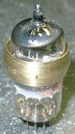
A variety of commercial “dampers” are widely available that fit onto the cylindrical section of the valve, and range from high-temperature silicon O-rings, to titanium C-rings with wheel pads [Ultrasonic], to heavier brass tube rings [Ref 4, Ref 5].
A simple homemade O-ring damper can be made using high-temperature silicone rubber engine gasket sealant - useable up to 230C, which is well above preamp valve glass temperature that typically is 100-150C. Or a metal tube of suitable inside diameter can be cut to a practical length and glued to the valve using the gasket sealer
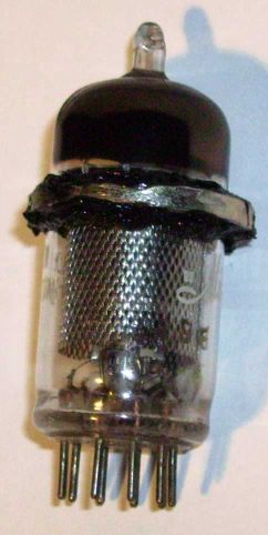
Place the damper between the top-most mica ring and the lower mica ring (or valve base if no lower ring), as that is the largest region of unsupported glass cylinder, and also forms the return structure for the top mica disk.
And let’s not forget electrical feedback!
Feedback around the preamp valve circuit involves comparing the input signal, say from the guitar pickup, to the amplified output signal sent to the speaker, and suppressing any internally generated distortion signal (which in includes the microphonic signals). Most guitar amps shun the use of electrical feedback, and purposefully introduce valve distortion, and so can’t use electrical feedback to help with microphonics.
Trying to determine how well the above techniques work is easy in a qualitative way - you either still hear the microphonic howl, or you don’t. Determining the quantitative improvement is another matter. Hopefully some more measurements can be made, or published, to guide us better.
References:
[1] “The measurement of Microphonic Effects in Vacuum Tubes”, R.Bird, Nov 1951. thevalvepage
[4] Tube_revelation.htm
This reference mentions the piezo-electric effect as a possible noise cause, however there is no mention of this mechanism in the literature and given the application and materials used, highly unlikely. -rr[5]damper.htm
[6] “Practical consideration in the design of low-microphonic tubes”, T.M. Cuningham, Dec 1954. triodeel
Addenda -rr
Actually valve microphonics are not so much rare as often un-recognised for what they are, and quite common on the service bench. While microphonics are normally a problem with low level preamp stages it is also possible, though rare, to encounter a seriously microphonic output valve.
All valves are microphonic to some degree but it is normally at such a low level it isn't obvious and a mild case of Jingle Bells escapes notice.
My method of isolating a microphonic valve (or other component) is to gently tap around the chassis and valves themselves with the rubber eraser end of a pencil, trying for a consistant tap force.
Microphonics can also arise from dry solder joints and damaged resistors, and most ceramic capacitors are microphonic to some degree.
Some more related reading;
- Duncan Amps on microphonics.
- Wikipedia on microphonics.
Added: 8/12/09
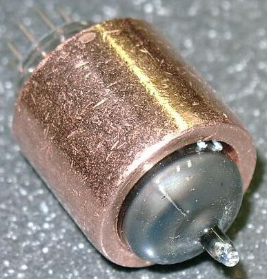
While the damper mass must be securely fixed to the valve so the damper mass becomes part of the valve, it must not be a tight metal-to-glass fit without some padding. This is because the valve glass and damper metal have different rates of expansion and the glass will crack, but you can fit a tight damper ring if the ring is cut to form a “C”, allowing an expansion gap.
Note that the vertical scale is logarithmic in decibels and also shows the acceleration in “g” (gravities, 9.8m/sec2).
“mg” is milligravities or an acceleration of 0.0098m/sec2.
|
|