|
http://www.ozvalveamps.org/noname.html | Last update:
22:55 7/06/11
<<<OzValveAmps |
Amplifiers that have no makers name or are obviously homebuilt.
(see also Playmaster)
Given a few vital parts a valve guitar amplifier isn't technically difficult to build.
Contains:New: 7/7/11
Joe Ampmangler's Radio & Hobbies 1954 build.
In the 1960's suitable output transformers were available over the counter, or wound to order from already established designs.
Power transformers were even more available from defunct 23-inch black and white TV's, and one chassis would provide most of the other components required such as high voltage electrolytic filter capacitors.
Most shopping strips had a radio and TV repair shop that stocked 12AX7's, 6BL8's and 6DQ6A's as they were common in black and white TV's.
So a lot of amps were owner-built either as a copy of an existing design, or as a mix and match of tone controls and other facilities to personal taste. These were built with various levels of skill - sometimes they worked out; sometimes they didn't.
New: 18/3/09
Thought you might be interested in this amp I built about 15 years ago.
The starting point was a very sad looking chassis rescued from a hard rubbish pickup. The transformers were the only items worth keeping. Being the tightarse that I am, just about everything else came from my junkbox. I made the new chassis and front panel. The amp was wired on second hand tagstrips and sockets. I did buy new caps and the knobs.
The circuit was a pretty standard 2x12AX7 + 2x6L6 with a 12AT7 reverb driver. The power transformer was an interesting beast, it had 2 identical HT secondaries originally series connected giving about 520v DC. This was a bit close for comfort with the caps and valves I had available so I paralled the windings and ended up with about 250v HT after setting the bias. This gave the amp a really nice early breakup without the ear bleeding volume.
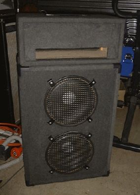
The speakers were a couple of 12 inch celestions I had lying around. The timber was all cut from stuff I had in the shed and the carpet covering was a trade for some repair work. All up I think the amp cost me about $40 in new parts. Unfortunately I was offered a silly amount of money for it and sold it not long after it was finished.
David
just thought i would show you the end results of the pro amp project i was building
she came into this world squeeling and motorboating, but with a few input jack replaced and the OT wires re-visted, and a lot of poking with a chop stick and valve moving, she hasnt done it since.it has a bright “woody” sound to it, very natural and nice overdrive just as you predicted by looking at the circuit
Source: Steve Kain
New: 24/9/06
The circuit of an amp designed by Phil Abbot of Brisbane, using one 12AX7 and two EL84's.
Source: Tim GarbuttThere's more than one way to build a guitar amp and here Tim Garbutt shows what you can do with a few odd parts and some ingenuity.
He also has some interesting muses on Aussie amps, safety, home building, and the way ahead.


Tim writes;
I have also been using the WES SA-2500 for the past few years with a pair of 6BM8's in push pull for a bodgey, experimental guitar amp. At a guess, probably developing 8-10W. I have had these flat out into a Celestion Vintage 30 (12-inch - 8ohm) reasonably often. It is surprisingly, an extremely LOUD combination. I guess the transformer is probably overkill for these valves and have never had any problems with it to date.
I've taken a couple of photos of the amp using the WES SA-2500 transformer with 12AX7's and 6BM8's (this must rate as one of the worlds dodgy-est “prototype” amps.
[No, the Warthog still holds that honor ;)]I used the guts of a Playstation-1™ wall wart (switch mode) power supply (subtly modified) to provide the DC (DC due to the dodgyness of this amp......no star earth here.....very embarrassing) filament requirements and a R-core tranny meant for audiophile preamps to provide the rest (thankfully these only just came within specs (with a...um.... slight tolerance...er.......um.....either way).
Surprisingly it all does sound reasonably good and the OT is still surviving regardless of the thrashing this amp gets from time to time. Hopefully this will reinforce the message that even the dodgiest amps containing these 100V line trannies can “potentially” hold their own against expensive purpose built OT's.
I have only just found and registered on the ANZAmps forum (it is great ...there are some very respected people there including yourself !! [blush] thank heavens there is an Australian forum) and am sort of involved in the recent 6DQ6 debate/discussion. I can see that some people there (like yourself, especially having built one of those old Playmasters) have had experience with these valves.
It seems that it is mostly Australians who seem to recognise that these (still) cheap and readily available valves (especially on e-bay, through a lot of American retailers (who still seem to think they are only any good for Tesla coil - Ionovac speaker drivers or for ham radio..... I've seen them for US$5ea NOS on some sites) and of course, through Retrovox here.) can make worthwhile guitar amps.
[Oi! What's wrong with a big Tesla coil, may I ask? ;)]Do you think there might be potential in creating or starting a new topic regarding a community/ANZamp forum based guitar amp project using these or any common sweep tube valves (single ended or PP....triode or pentode out (or both)....low or high power (or both))????.......Maybe also emphasising HV safety (unfortunately a lot of people who do build valve amps haven't done any formal training and are seemingly getting younger/less experienced with HV).
[I do, and I think it's a great idea.]Not many forums or sites really put any emphasis on safety....as you know, valve amps aren't cheap...and are the “holy grail” for guitarists (especially “bedroom-bashers” looking up to the internet “Pro's” and audiophiles (that IS a rude word) alike ...often attracting those that can least afford/be bothered with doing any course.....or..... at the very least be patient enough to gain some experience with lower powered electronics first, let alone listen to anyone with electrononics/electrical experience......this is especially so when it comes to the redesign/build and modification of old, potentially very hazardous amps).
I'm sorry,..... I foremost have to teach/preach safety in my job and unfortunately it rubs off in this great hobby (and especially irks me, i've had to revive/administer first aid to a few....fortunately only mild shocks or mild RF burn) in high voltage electronics with beginners/novices on a public domain....i'll try to control myself in future :-).
[HV safety is vital, death obstructs tinkering, but too many sites take the sex-ed approach of “just say no”. Working on amps, valve or solid-state, has real risks, but they are more in common with mowing the lawn than skydiving - don't touch the blade while it's running. The risks are controlable and well worth the rewards.]
Having said all that, maybe, even, incorporate some common, off the shelf 100V line trannie in the project (as you know, it seems that the primary impedance doesn't necessarily need to be too high for reasonable power for some sweep valves (low voltage-decent current handling). Also, that although most of these sweep valves can handle high voltages (or power for size like EL509/519 etc, most OTL potential valves).
They can still better (at least better than most popular audio output valves and still be clean...as you know most people really only need their “tone” in the preamp/splitter/effects loop stages.....unless they are playing the MCG and not be able to be miked up, how many really need “their sound” in the output stages these days ?) .......handle reasonable amounts of current.....and should also be durable enough for low power output class A amps (single output valve....maybe some real output tone there).....I guess most of these valves were purposely built to try to survive for the life of the TV set under some very unforgiving circumstances (CRT/PSU/vertical deflection/passive component changes, so should make for some “bullet-proof” audio amps (as far as valves are concerned compared to SS).
So far as Australian ingenuity/electronics/engineering is concerned...we make their old stuff perform better than American new multi billion dollar stuff :-)...why not continue this ?)......and especially so if we are able to collectively come with something very good.......maybe even potentially organise a group buy for a lot of their NOS stocks of 6DQ6's/obscure sweep valves or at the least show amp builders that they can potentially be as good as, or better than 6L6's or EL34's.
I am still totally convinced that the depth of experience in Australia is as good as anywhere in the world. It would be especially good to put a bit of a spotlight on some of the older Australian amps (potentially even increasing the value of them in the world market...(as opposed to some of the stuff that Fender (most of the post-black face) and Marshall (most post JCM800) have produced and still command high $$ for us......
A few years of internet searching has revealed very few overseas based 6DQ6/sweep tube guitar amps. It seems that only in the past few years that sweep tubes are having their day, in general. (especially OTL and audiophile). There really are some decent Australian amps that deserve their “day in the sun”.
Best Regards
TimMy responses to some other points Tim raised;
} tg} I also remember once reading an article about how
} most modern 100V line transformers use “grain
} oriented” laminations,
}
} This was a fairly significant development at the time
} and some of us were initially sceptical that such
} small G.O. trannies could do the same job as the
} hulking steel bricks we were used to.  Before that you
} would expect an o/p tranny to be about the same size
} as the power tranny, then suddenly we have something
} quite a bit smaller that does the same job.
}
}
} tg} 6DQ6's are still readily available and very cheap
} on ebay and many online stores (especially ham radio).
}
} I think David Crittle of Retrovox.com still has a few
} too.
}
}
} tg} I have a pair of large Ferguson OP617 transformers
} that I will experiment with when I get time.
}
} All I can tell you is that they are (OTnnn) Fergy
} output transformers for sure, and date after 1970 as
} their number series hadn't quite got that far yet and
} I have no later data.
}
} (mind you there were a number of existing designs that
} you could buy 'to order only' which they didn't
} advertise.  You rang up, told them the bottle and
} power level, and discussed with an engineer what they
} already had in the filing cabinet.  They never failed
} to find one for me.  Sent off about $120 (~$1/watt) or
} a couple of weeks pay, and six weeks later - kerthump!
} - it arrived at the local postoffice and you had to go
} and collect it and some dirty looks.  Otherwise it was
} $400 and 12 weeks for a 'special', as I recall.)
}

[re: 100 Volt tranny ratings]
} Well, as you can see from that page [*], I was assuming
} “20W” meant 20 watts rms, not “peak2peak programme
} music power with a following wind”.
}
} The real world question is do they get too hot?  You
} can see what I did; the onset of clipping into a
} resistive load for an hour or more (and even a
} keyboard amp gets a rest every few minutes).  Hot is
} to be expected, burn your fingers isn't.  I put in a
} bigger tranny because it was someone elses amp, but if
} it's your own it's entirely up to you what is okay or
} not.  Given that they are so cheap you can either
} decide to blow one up now and again for some
} transformer 'grind', or fit a bigger one (or two) for
} more comfortable operation.
}
}
} I still take my hat off to Paul Cambie [*] for his
} inspired work, all I did was try to make his discovery
} better known, and try to encourage others to think
} outside the frame as he had done.
* 100 Volt Line trannies applied in valve output service.
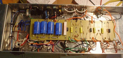
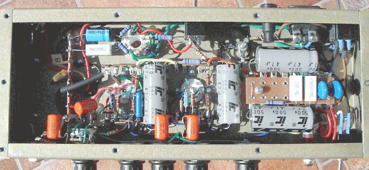
Bought this on ebay a month ago and got the circuit and photos done pretty quickly so it is a bit ugly but better than not at all. No names on anything bar the output txfr which is A&R with lots of taps.


Traced circuit of the above. Errata: the main rectifier diodes should be the other way around. The mid-point of the 470k's on the power valve grids should go to ground.Source: Derek Lark
Shaun tells the story...
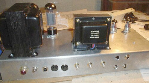
Thursday, April 07, 2005I have just built my first homebrew amp from scratch.
Since I had a couple of trannies from a butchered 10W single ended amp hanging around, and I found a great little aluminium chassis in the trash, I figured it would make a good basis for a small practice amp while learning some more about valves.
So I went to ax84.com and found a sweet looking schematic [30kb gif] for a single EL34, cathode biased amp with a Marshall style preamp based on 3 gain stages and cathode follower feeding a typical Marshall tone stack.
Since the chassis is so small, layout was going to prove to be critical. So I drew up a layout on the computer first, that gave me a good indication of what was to fit where. I ordered most of the components from Hoffman amps. They have a great range of bits and aren't out to rip you off like some parts suppliers. Kudos to these guys and the ax84 web site/forum.
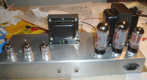
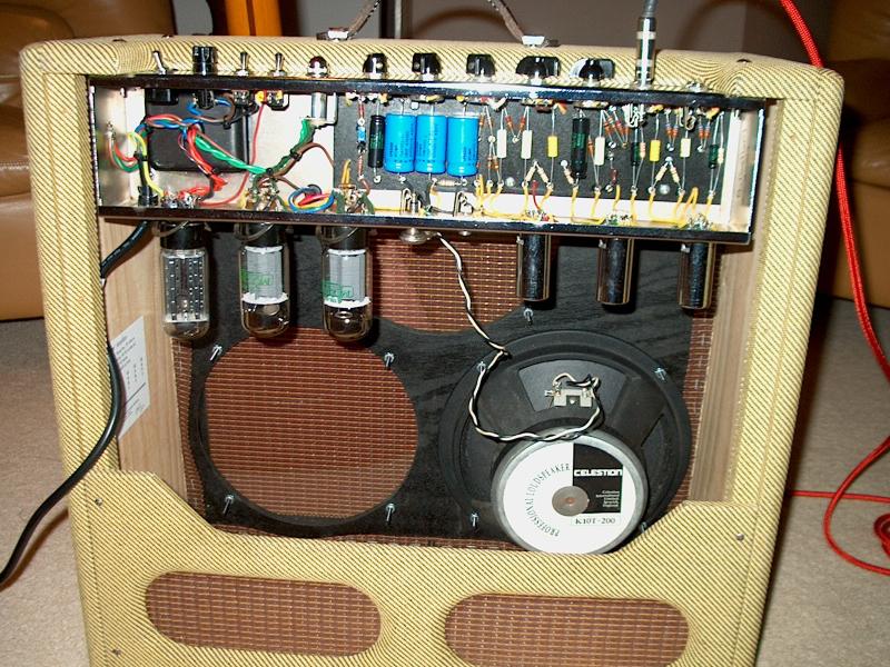
Anyway a bit of drilling and a few nights arched over a soldering iron and the result can be seen in the pics attached.
The thing started up straight away. A bit noisy at first though. I moved some parts added heater hum reference resistors and rewired the heater wiring to your sites specs and presto! Quiet as. I was really expecting some hum and oscillation problems especially considering the proximity of some parts.
I followed a star ground system and used as many ideas that I could recall from seeing the guts of other amps and from reading web sites such as your own.
I am even more surprised at the performance of this thing. It sounds absolutely glorious! A real Marshall 'clang' on the lower gain settings and a terrific roar with some gain dialled in. Boosted with a clean boost pedal and it's tight and chunky with singing lead tone.
I haven't measured output power yet but we've jammed with some loud drummers with plenty of volume to spare (in a small practice space). I am running it through a closed back 2x12 with Celestion G12H30's (100dB @1m sensitivity). I've got the E34L (30W version of EL34) biased at around 85mA with 275V on the plate.
So my little 'practice' amp has actually knocked my Marshall 30th anniversary head off it's pedestal. And at a cost of around $100 of parts! ;)
The guys in the band and all my muso mates really love the tone and prefer it to my much more expensive Marshall. I'm getting questions about building more.
Anyway, just thought you might be interested. I'm sure you'll agree that the ax84 site is a great idea for anybody like me wanting to start out making basic amp designs. These amps have all been designed by members and are discussed on the forum. Great fun!
Thanks to Shaun Helps
Take a close look at Shaun's underchassis. That's what I mean by “elegant”. This neatness (and good operation) come from planning. I used EasyTrax, a PCB layout programme, to build both the Midranger and Siamese W-bins in the computer before I made single cut. This exposed several problems that were addressed before work started, and some modifications to the original design were “built” and “tested” using math models.
How much power is enough? A while back I mixed a gig where the violinist was far too loud using a nominal 15 watt amp with 10-inch speaker. After I got comments from people who were 100 yards away they the only thing they could hear was violin, no kick or bass, I checked the amps' power output - a mere one-and-one-half watts at clip.
The AX84 circuit.
This is a very high gain preamp, held in check by three gain/volume controls along the path. Individual stage gain is x50-60 or 34dB so the wide open gain is about 100dB or 200,000 times. That's around 50 microvolts input for full output so you can understand why Shaun was expecting some stability problems at flat out. With this sort of gain available in a compact layout it is not unusual to see a shielding plate over the input jacks, or even surrounding the entire input stage.
By careful setting of the three level controls it should be possible to choose which stage limits, thus providing a tonal range between crunchy front-end clipping and more mellow power-stage overdrive.
Notice the values of cathode by-pass caps are quite a bit lower than the traditional 25uF/25V which will give some low end roll off. As a low power amp it would normally go in a small open-back case and this roll-off will help to prevent the speaker frapping on bassy notes.
The triode/pentode switching of the output stage is a very neat trick, but I'm afraid the point of the double-pole standby switching is a mystery to me, however the overall circuit looks like a well-developed design.
A small drafting error: the heater for V3 is drawn hopping over the heater power lines which it obviously connects to.
Backyard builders sometimes copied commercial designs, building them onto whatever chassis was available.
My original drawing for this one is annotated 'sort of Moody, built on Playmaster 102 chassis'.
I don't remember much about this head except that it was used for bass, and that it was the first time I witnessed a 6CA7 do its flashbulb imitation, thankfully only at a practice.
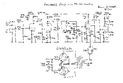
About as basic as they come, only four valves.
Two inputs mixed to a straight two-stage preamp and volume control. This consists of a single 12AX7, both sections in cascade to the volume control
Passive 2-way Baxandall tone control, the bass section at much higher impedance than normal.
This all-gain-before the volume control, and that before the tones, are both unusual.
No power supply details are available.
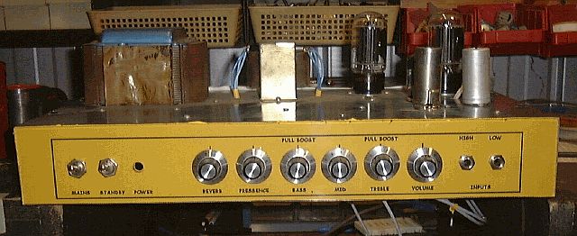
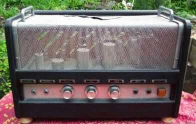
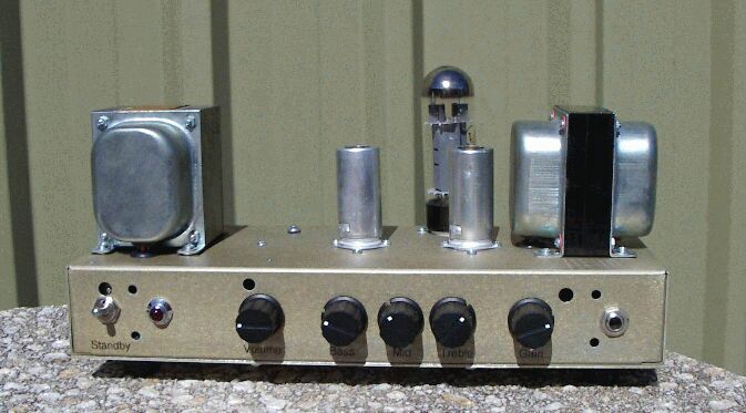
Refurbished 2000

Inverted chassis
2 input each to
2 channels
vol, treble, bass
Fender-style tone controls
Rear-mounted bass boost 'deep' switch (excessive)
2 x -bias 6CA7/EL34's
Power, standby, neon indicators
Single speaker connector
 Made from old chassis. On off, pilot light Bass and Treble High/Low inputs 12AX7/12AU7/6BQ5 3.75/8/15 ohms outputs
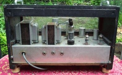
Note the orientation of the power and output transformers. They are more generally mounted with crossed axies to avoid direct hum pickup in the speaker circuit. Better at opposite ends of the chassis where they tend to balance the head better for carrying. The flux shorting strap can just be seen crossing the top of the power transformer.
The output pair looks rather like a pair of 6CM5's.
Source: e-bay
More photos can be seen here.
By Alan Bellert and Andrew McWhirter.
Representing some classic Aussie inginuity after Heath Robinson, and making the best of what you've got, Anthony Ralph's creation might not be that practical for gigging, but it makes a great test bed.
New: 2/7/06
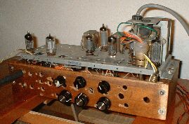
I'm wondering if you can help me with this little beautly I purchased last week. I was told it was made in Sydney. Possibly a small Harp amp
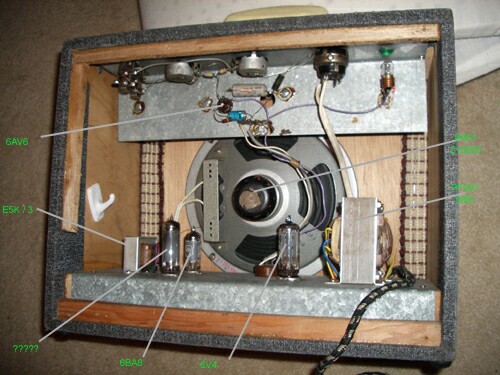
The valves that have marking are; 6AV6, 6V4, 6BA6, and Blank ???? ( Tall rather thin valve 7 pins )
Speaker: Rola 8H01 [ 8 inch ] - Dated 23/2/1963
Power Tranformer PF 201 - dated 9/63
Output Transformer ESK / 3 [actually E 5k/3, being 5k ohms to 3.5/4 ohms]
It looks rather home made inside with Galvanised Iron sheets bent for the chassis.
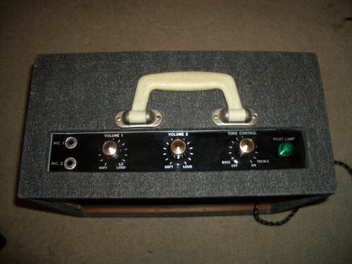
It must have had a name plate on the bottom of the front inside lip and also a small square plate on the back cover.
It has two channels both appear to be linked through the same 6AV6, two volume controls and a tone control with the on / off switch.
Quite good tone with guitar and reasonable volume I am assuming a couple of watts max.
It would be great to know who built it?
Any help or direction would be greatly appreciated.
Kind regards,
Graeme
If you have any information about these amplifiers, or have a build you would like to submit, please see How to Submit.
|
|


