Cheap Output Transformers
The output transformer in a valve guitar amplifier is perhaps the most difficult component to obtain if you are building, or to replace in repair, but there may be an answer closer than you think.
Contains:
Background
As it happens, audio transformers are still in use as 100 volt line-to-speaker level adjustments.
These trannies have various taps on the primary which are marked in power levels, 10, 5, 2.5 watts, etc. These tap markings mean the amount of power delivered to the speaker load from a 100 volt PA line.
A big pat on the back for Paul Cambie for spotting that the arrangement of the tappings on some line transformers allows them to be used as valve output transformers. This is creative technishing at its best. His page on his investigation of the M-1115 in this role led me to have a look at other such trannies.
Credit also to Grant Wills for demonstrating that theory and practice agree by building a stereo using two of these and two pairs of 6CA7/EL34's.
Here I look at a number of available trannies and how they can be applied, including repairs to a Fender Bandmaster and a Fender Deluxe.
Baseline
To start with here is the data for some typical valve output transformers as a reference point. Notice that the required turns ratio, Vp/Vs, is between 20:1 and 35:1.
| Valve |
Pout |
Zp-p |
Zsec |
Zp/Zs |
Vp/Vs |
| 6V6 |
14W |
8k |
8 |
1000 |
31.62 |
| 6V6 |
10W ul |
10k |
8 |
1250 |
35.35 |
| 6CA7 |
48W |
3.5k |
8 |
437.5 |
20.9 |
| 6CA7 |
54W |
3.5k |
8 |
437.5 |
20.9 |
| 6L6 |
55W |
5.6k |
8 |
700 |
26.46 |
Zp-p is the required impedance, plate-to-plate
Zp/Zs is the primary to secondary impedance ratio
Vp/Vs is the voltage and turns ratio
ul is Ultra-Linear screen connection
15 watts
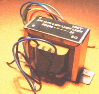
Altronics M-1115
Frequency response: 30Hz - 20kHz ±3dB
Secondary: 8 ohm
Primary: 1.25W, 2.5W, 5W, 10W, 15W
| “Pwatt” tap |
Volts in 8 ohms |
Vratio |
Zratio |
Zpri (Zs=8 ohms) |
| 1.25 |
3.16 |
31.62 |
1000 |
8000 end 8kp-p |
| 2.5 |
4.47 |
22.36 |
500 |
4000 ul |
| 5 |
6.32 |
15.81 |
250 |
2000 ct |
| 10 |
8.94 |
11.18 |
125 |
1000 ul |
| 15 |
10.95 |
9.12 |
83.33 |
666.66 (no use) |
| 0 |
0 |
0 |
0 |
0 end |
ct = center tap
ul = ultra-linear screen tap
end = plate connections
This transformer would seem ideal for a pair of 6V6's, even providing taps for ultra-linear screen connection if required.
The calculation method is as follows:
The tapping powers are the power in the nominal load, in this case 8 ohms. The voltage in a resistance for a given power is given by:
E = Sqrt (P x R) ---(1)
Assuming the transformer is fed from 100 volt line, the voltage or turns ratio is given by:
Vin/Vout ---(2)
Where Vin is 100 volts and Vout is E from (1) above.
The impedance ratio is the square of the voltage or turns ratio:
Zin/Zout = ( Vin/Vout )2 ---(3)
The primary impedance plate-to-plate is the impedance ratio times the load:
Zp-p = (Zin/Zout) x RL ---(4)
Not just theory
|
59°C and climbing.
Fender Deluxe fitted with a M-1115 on one-hour soak test.
6V6's,
Pout = 16W (clip),
RL = 8 ohms,
f = 1kHz,
Tamb=28°C.
Transformer temperature stabilised at 65°C.
In the flesh this is a very small core for 15Wrms and this is reflected in its high running temperature. The dead tranny that came out was about twice the size. I definitely wouldn't use it in bass duty.
While this delivers the goods, on the results of this test the next transformer would seem to be a better proposition. (see below)
|
|
20 watt
Altronics M-1120
Frequency response: 30Hz - 20kHz ±3dB
Secondary: 4, 8, 16 ohm
Primary: 1.25W, 2.5W, 5W, 10W, 15W, 20W
| Pwatt |
V in 8r |
Vratio |
Zratio |
Zp,8ohm* |
| 1.25 |
3.16 |
31.62 |
1000 end |
8000 8k p-p |
| 2.5 |
4.47 |
22.36 |
500 |
4000 |
| 5 |
6.32 |
15.81 |
250 ct |
2000 ct |
| 10 |
8.94 |
11.18 |
125 |
1000 |
| 15 |
10.95 |
9.13 |
83.3 |
666 |
| 20 |
12.64 |
7.90 |
62.5 |
500 |
| 0 |
0 |
0 |
0 end |
0 end |
* When a sample arrived these impedances were written on the box.
The range of secondary tappings multiply the possibilities. By “misconnecting” the load a range of primary impedances become available. For example, if an 8 ohm load was connected to the “16 ohm” tap the primary impedance would be half; to the “4 ohm” tap, double.
Because of the power headroom this tranny may be suited to a “clean” 6V6 output stage.
The Deluxe above was refitted with this tranny.
Tamb = 30°
T = 54° after 1 Hr at clip (16W) into 8 ohms, 1kHz.
I'm inclined to think the power ratings on these two trannies are something like 'peak watts' because the “15W” one was uncomfortable at that RMS power level while the “20W” one is about right.
25 watts
WES Components SA-2500
Frequency response: 30Hz - 20kHz ±3dB
Secondary: 8 ohm
Primary: 1.625*, 3.125, 6.25, 12.5, 25.
| Pwatt |
V in 8r |
Vratio |
Zratio |
Zp,8ohm |
Lead |
| 1.625* |
3.61 |
27.74 |
769.23 |
6154 |
|
| 1.5625 |
3.54 |
28.28 |
800 |
6400 end |
red |
| 3.125 |
5 |
20 |
400 |
3200 |
green |
| 6.25 |
7.07 |
14.14 |
200 |
1600 ct |
grey |
| 12.5 |
10 |
10 |
100 |
800 |
blue |
| 25 |
14.14 |
7.07 |
50 |
400 |
yellow |
| 0 |
0 |
0 |
0 |
0 end |
black |
Sec: black, blue
* NOTE: the “1.625W” marking in the catalogue, box, and transformer itself seems to be (fortunately) in error. Logically it should be 1.5625W, and when driven with 12VAC on the speaker winding the red/black voltage symmetry w.r.t. the grey center tap is in fact better than 1%.
Winding resistance is another matter, being 325 ohms grey-to-black and 80 ohms grey-to-red. This is not good, but these values are only a fraction of the total load impedance and shouldn't be a problem in guitar amp service. In fact conventional output transformers have different resistances each side because they have the same number of turns around differing winding radii.
By itself this tranny doesn't seem very useful. But using a pair with series-connected secondaries we can get a more useful 3k2 ohm plate-to-plate impedance and a 50 watt power level for EL34/6CA7's.
With the secondaries in parallel the 6k4 ohm p-p is a reasonable match to a pair of 6L6's.
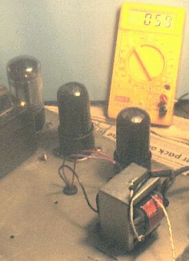
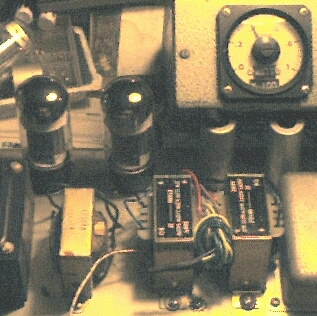
It's a goer! A pair fitted to a blond Fender Bandmaster, making 40 watts at clip even using old low-emission 6L6's.
After an hour on soak the trannies were no hotter than expected, 50°C at 28°C ambient, however they do “talk” more than normal. Most of the heat seems to be coming from core losses rather than I2R copper losses in the windings, so the difference in resistance does seem insignificant.
Leo even provided four unused mounting holes which only required the tranny frame sides to be splayed slightly, and only a couple of leads had to be extended - very straightforward.
The inductor, left, is the HT filter choke.
The striped wire is a temperature probe.
Test frequency 1kHz, RL = 8 ohms.
|
|
40 watts
Altronics M-1130
Frequency response: 30Hz - 20kHz ±3dB
Secondary: 2, 4, 6, 8 ohm
Primary: 5W, 10W, 20W, 40W
| Pwatt |
V in 8r |
Vratio |
Zratio |
Zp,8ohm |
| 5 |
6.32 |
15.81 |
250 |
2000 end 2kp-p |
| 10 |
8.94 |
11.18 |
125 |
1000 |
| 20 |
12.64 |
7.90 |
62.5 |
500 ct |
| 40 |
17.88 |
5.59 |
31.25 |
250 |
| 0 |
0 |
0 |
0 |
0 end |
This table shows some of the possible plate-to-plate impedances that can be obtained with different loads on the secondary taps.
| Tap |
Zload |
| |
4 | 5 |
8 | 10 |
16 |
| 2 |
4000 |
5000 |
8000 |
10000 |
16000 |
| 4 |
2000 |
2500 |
4000 |
5000 |
8000 |
| 6 |
1333 |
1667 |
2667 |
3333 |
5333 |
| 8 |
1000 |
1250 |
2000 |
2500 |
4000 |
5k3 will match 6L6's.
3k3 or 2k6 will match a pair of 6DQ6B's for 40 or 60 watts (and a bit of overdriven transformer grind. ;)
Three of these simply wired in parallel would provide a reasonable match (2k vs. 1k75 p-p) to a quad of EL34/6CA7's for around 100 watts.
60 Watts
Sadly the Altronics M-1136 60 watt version doesn't have a center tapping. Perhaps someone will contrive a cunning way around this, but it seems like a dead stop to me.
120 Watts
Altronics also have a 120W torroidal 100 volt line transfomer with two identical primaries and secondaries. Because the power level is so high the basic turns ratio is very low and even mismatching a 16 ohm load to the 2 ohm connection the highest obtainable plate-to-plate load is only about 500 ohms.
This is of little interest unless you are contemplating a really big bruser using a couple of these and rows of output valves (or maybe a pair of 4CX250's ;).
Higher powers
Being typically power-mad, I went on to look at how far this happy discovery could be stretched. It's seldom done, but placing a pair of transformers in parallel opens up some possibilities.
Both center tapped primaries have to be connected in parallel so they both still carry balanced DC. But the speaker secondaries with their taps are up for grabs.
If you simply connect two (identical) transformers in parallel the impedances on both sides stay the same because the turns ratio is unchanged, but the power handling has been doubled. This if fine if the impedances are what you want but in some of these cases they aren't.
It's all very well having a 6k plate-to-plate to 8 ohms tranny when you need 3k p-p into 8 ohms. One answer is to use a 4 ohm speaker connected to the 8 ohm winding, then the primary will also see half the impedance. But generally the speaker impedance is already fixed.
If, instead of connecting the secondaries in parallel we connect them in series we have changed the effective turns ratio of the combination, then each winding will see 4 ohms of an 8 ohm load, and the primary impedance will also be halved. So now we can get our desired 3k p-p to 8 ohms at 50 watts.
There are also some possible primary connections that use less than the whole primary winding. You are on your own here.
Some points to remember:
You must keep everything balanced. You can't, for example, use one transformer in each anode circuit because both will saturate on unbalanced DC.
Similarly you can't mix different secondary windings, such as connecting a 4 ohm winding and a 16 ohm winding trying for an oddball plate-to-plate. You'll get it, but the powers will be unbalanced in the trannies.
You don't have to connect an 8 ohm load to an 8 ohm tapping. If you require half the primary plate-to-plate impedance then this will match to half the secondary marking.
There is no law against, say, connecting three 15 ohm speakers in parallel to get a working load of 5 ohms if that produces the desired primary impedance.
The windings between the secondary taps are available, and provided you do the same thing on both transformers, this should expand the range of options.
And since they are inexpensive, there is no reason why you can't take this further, using three or four transformers for impedance matching or power handling reasons.
This is far from a complete list of the possibilities. If you have a requirement that isn't satisfied here, get your thinking cap on!
If you have actually applied a line transformer like these as a valve output transformer, please click here.
What is 100V line?
Genuine “Public Address” systems are in use in office buildings, factories, stores, stations, airports, and so on. (strictly speaking bands use “sound reinforcement” not PA)
In a small factory an amplifer with an 8 ohm output might be wired effectively to a few speakers around the place.
But as the area to be covered gets bigger and the speakers more distant from the amplifier cable losses quickly become intolerable at low impedance.
Enter the 70 volt and 100 volt line. The output of the amplifier, valve and transistor, is generally fed to a transformer that has a secondary winding arranged to produce 100 volts at full output.
This is then run, often in mains cable, around the site to be covered.
Now the problem is that different areas need different power levels depending on the background noise - what is inaudible in the press shop will be too loud in the toilets.
So various ordinary low-impedance speakers are coupled to the line using a transformer, and that transformer has a range of primary tappings to set the power level on the speaker side.
If you want more power from the line you tap down to present a lower impedance and intercept more; less and you tap up. Some speakers even have a multi-pole tap selector switch for level setting.
Unlike an 8 ohm system there is no attempt to match the load impedance to the amplifier, in fact the mismatch is used to limit the load power.
This is the same as the domestic power mains where, if you matched the point-oh nothing output impedance of the power station you would get its entire power output. This is called the Maximum Power Transfer Law, so be thankful your toaster doesn't match to the mains.
 <<<OzValveAmps
http://www.ozvalveamps.org/optrans.html | Last update:
21:30 24/09/05
|