When you come across an old amp chassis in the dusty back corner of some shed, one of the first questions to pass through your mind (apart from “how can I score this?”) is “are the trannies okay?”.
The reason is that the power and output transformers are the heart and soul of a valve guitar amp. These are the most expensive components and the most difficult to replace or repair.
Just a chassis with two good transformers is a real prospect, but even a previously working amp with an unserviceable transformer is a nightmare.
Resist the temptation to just plug it in and see if it boogies. It may, but if it has been out of service for a year or more there is also a bad chance of doing some serious damage to the amp and your plans for it. It's a poor bet with a serious downside if you are unlucky.
Visual inspection
Firstly, use your eyes. This should always be your first move working on any piece of gear - give it a real good scrute before you do anything else.
There will be a reason the amp was banished to the back shed and the chances are that if you look long and hard enough you will see clues. But take heart, many amps have been banished for very trivial reasons and often respond well to a bit of care.
Are the trannies obviously damaged?
Worst case is that one (or both) has suffered a cook-up. This generally leaves burnt tarry gunge on and around the tranny, and it can look burnt like it has been through a fire.
Sometimes you will find a mess like this on the chassis around the tranny but no sign on the tranny itself. This means that the previous tranny burned out and has been replaced. In many cases this replacement will be a ring-in that was to hand and may be quite unsuitable.
A tranny that has rusty laminations may look a bit sorry, but rusty laminations by themselves are seldom the cause of any significant electrical problems.
Are there grinch marks on the winding, perhaps caused by being tossed around with other hard objects? A transformer may feel solid like a brick but the copper windings are actually quite fragile and don't like being hit with hard objects. This will damage the thin enamel insulation on the winding wires and may cause shorted-turns, effectively killing the tranny.
For much the same reasons you should not re-use winding wire recovered from a tranny or choke except in non-critical applications - it's insulation has been damaged simply by winding and un-winding.
Sustained overload can cause similar damage by burning this enamel off the wire.
Resistance tests
The next step is to test the windings for continuity and short circuits. This can be done using the resistance ranges of an ordinary multimeter or cheap yellow DVM, but a high-voltage Megger-type insulation tester, battery or hand-cranked, is ideal.
A typical guitar amp power tranny has three windings, a primary for the mains input, a high voltage secondary which will often have a grounded centre-tap, and a heater winding. In bigger amps you might find additional heater windings which may also be centre-tapped, and sometimes a winding for a bias supply. (there may also be a wire, often light green, that is open circuit - see electrostatic screen below)
The heater windings are normally wound using thick enamel covered copper wire, and the higher voltage windings with fine enamel wire which is internally terminated and brought out on stranded hookup wire.
Older trannies, particularly of the drop-through type, often had their own terminal tagboard with the voltages and currents written or stamped in.
Winding continuity
Before you can do any meaningful tests the secondary windings have to be isolated from the circuits they drive so you are only measuring the resistance of the winding.
In some cases the heater circuit can be isolated by simply removing all the valves, not forgetting the pilot light if fitted.
Pulling a valve rectifier will generally isolate the high voltage winding, but solid-state rectifiers will normally need to be un-soldered somewhere.
The mains input primary should already be isolated from everything else so you shouldn't need to unsolder that.
Once isolated you can then proceed to measure the resistance of each of the windings.
We need to check all the windings for continuity. Heater windings will show a very low resistance from dead short to a few ohms, while the primary and high voltage windings may show anything up to about 100 ohms, depending (e.g. the two sides of a center-tapped winding may differ in resistance by up to 10%). Any winding showing a resistance significantly higher than this is suspect (but always triple-check any suspect measurements).
Leakage
Remember, you also have resistance and if you do high resistance tests holding the wires to the probes with your fingers you will only be measiuing your own resistance (~20k). Use clips.
Next, using a high-voltage tester like a Megger or your multimeter on highest ohms range, check the resistance between the various windings. Ideally all should be totally isolated from each other, hundreds of megohms or more.
You should also test each winding to the core and transformer frame itself as it is possible for a winding to fail to the frame (ground).
A tranny with any measurable leakage between windings may have picked up some moisture. These can sometimes be recovered by baking out. This means heating the tranny to about 50°C for some hours to drive any moisture out, but it's a slow process.
You can try a very slow electric oven, on top of a hot light fitting, or on a sunny window sill, depending on how much of a hurry you are in. Don't use a gas oven because they are humid, and don't try to microwave it ('cause the microwave won't like it).
Electrostatic screen
Some trannies are fitted with an electrostatic screen between the primary and the other windings. This provides a kind of in-built line filter agains mains-borne noise being capacitively coupled to the secondaries (e.g. drill whine).
This is often a solitary green wire that goes into the middle of the windings and has no continuity to anything else. Sometimes marked “E.S.” on quality transformers. If you have such a lead left over after all the others have been accounted for then it is likely and electrostatic screen and should be connected to ground, the chassis mains earth point.
Flux shorting strap
Not part of testing, but you will come across mains transformers that have a heavy copper strap fitted around the outside. This is a deliberate shorted turn fitted around the outside of the transformer to short out any magnetic flux leaking from the transformer.
While this makes the tranny a bit less efficient, more lossy, it kills the mains frequency magnetic field that leaks out of the tranny laminations and can cause problems in nearby circuits. These include direct induction in output transformers, inducing circulating currents in earth-loops, and direct modulation of electron beams inside valves.
Shorted Turns
New: 13/12/10
One fault a transformer can develop is a shorted turn or turns, where the insulation between turns or winding layers has broken down. This is a fatal failure and requires a rewind to repair.
These turns are intimately coupled to the transformer magnetic circuit and act just like a proper winding, but with a short circuit across it, hogging all the available power.
In some cases, lower power output tranformers in particular, diagnosing a shorted turn can be difficult. Joe “Ampmangler” has identified (courtesy R.G. Keen of geofex.com) a simple trick that should help a lot.
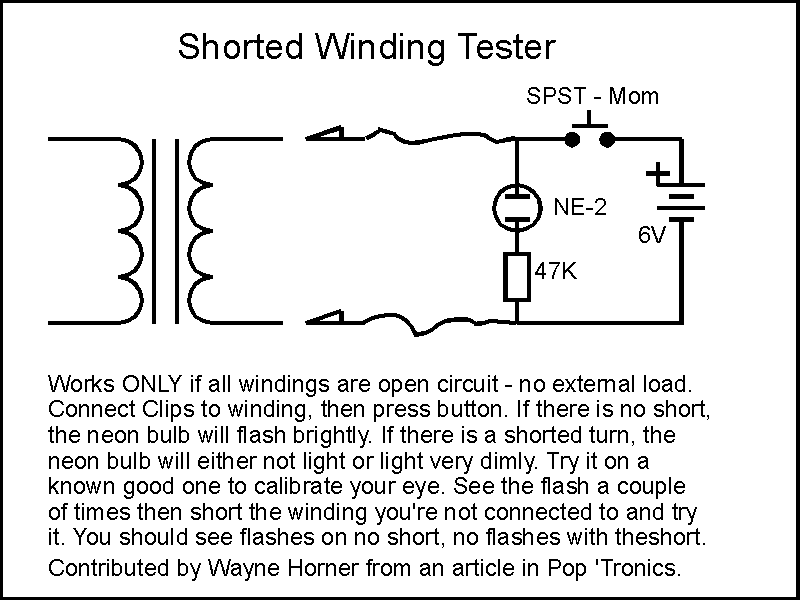
This works the same way a car ignition coil works. When the button is pressed a DC current starts to flow in the connected winding. This current rises according to the Laws of Induction until it gets to a value where it is only limited by the winding resistance. Even in a very big transformer this should take less than a second.
Now a steady current is flowing a steady magnetic field has been established in the transformer core.
When the button is released the current is interrupted and the magnetic field collapses quite suddenly, inducing a very high voltage in the windings, quite enough to cause a connected neon to strike and flash.
If the transformer (this applies equally to iron-core HT filter inductors) has a shorted turn then the collapsing field is both absorbed and retarded by the counter-current induced in the shorted turn, that the back-EMF this short-circuit current itself induces opposes the collapse, so you don't get high voltage or a flash.
Caution: any external connections will defeat the test and may damage something through overvoltage. That also goes for you being connected to any of the windings when the current is broken. Like a car ignition coil it won't kill you, but most of the transformers we deal with are magnetically bigger and store more energy to give you an even bigger boot.
Source: Joe “Ampmangler”
If all is well, this is the point where we get out our trusty load-limiting lamp lead and put some real voltage on the power tranny.
But first

You must check and clean up the mains input wiring, or bypass it safely using your killer lead. Never omit a chassis ground connection during live work.
Remember: the limiting globe is there to protect the tranny, not you. The tranny primary and high-voltage secondaries will be at dangerous voltages. There is no shame putting a newpaper, plastic bag, or patch of gaffer tape over anything you really would really rather not touch.
Tip: For these sort of tests it is better to make the required connections cold, soldering or with clips, then power up for the actual measurement. This avoids probing a live chassis with possible probe slips while you are distracted reading the meter. Slower, but much safer if you are not used working with high voltages.
In all cases the lamp may blink or flash at the moment of switch-on. This is caused by magnetising inrush current and depends on the type of core and the mains voltage at the instant of switch-on. This is normal.
Starting, as always, with the lowest power lamp, say 15 watts, we switch on and observe.
With a small power tranny the lamp will dim and perhaps go out altogether. Shorting any of the windings (carefully!) should make it light to full brilliance.
Any residual lighting is due to the transformer magnetising current, and this is generally proportional to the size of the tranny, so a large amp tranny will cause it to light more.
If the lamps lights brightly and shorting a winding makes little or no difference, then the transformer may have a shorted turn, but recheck that it is fully disconnected first and that you haven't missed something like a pilot light or hum-dinger connection. A shorted turn is generally the end of the road for a tranny (and leaves you up the creek).
Output transformer
Let us assume that we have got to this point, as I did with the Chandler, and everything is checking out okay, no obvious problems with the power tranny.
How can we test the output tranny?
This is perhaps the simplest and roughest way to test an output transformer, requiring only a multimeter or DVM.
On the plus side this simple test returns a lot of information. On the minus side the low frequency used, mains 50Hz, means that the results have to be interpreted cautiously.
The basic idea is that we drive the output transformer by connecting the 6.3 volt heater winding directly to the speaker winding on the output transformer.
The caviat is that many output transformers don't perform well down at 50Hz. A tranny in a nominal bass amp may give very realistic figures, but a tiny tranny from a small practice combo may not have a lot of response at this low frequency and not give a clear indication of faults such as a shorted turn. While some results may be rubbery this test is still useful to sort out the seriously dead ducks.
Again, the output transformer must be fully isolated. If the output tranny has a selection of output impedances, feed the heater voltage across the largest one, typically 15 ohms, using the whole winding.
When powering up use the 15 watt load limiter first. You can use a larger wattage lamp to bring the voltages up a bit if they are too low to easily measure, the heater line in particular.
The voltages you are particularly interested in are the driving heater line voltage, and the voltages either side of the center-tap - caution: these may be hundreds of volts.
Carefully and accurately measure and record the voltages on the speaker and valve side of the output tranny. If there are no signs of distress you can step up to a higher wattage lamp for higher and more accurate voltage measurements, but do not run this arrangement for extended periods, only a minute or two at a time.
You should now have three voltages; the voltage on the heater line driving into the speaker-side of the output tranny, and the voltage measured either side of the centre-tap on the valve side. These latter two voltages should be close to equal.
Turns ratio
Since output trannies are specified in terms of primary and secondary impedance we need to convert our voltage measurements into an impedance ratio.
The first step is using these voltages to find the voltage ratio (and thus the turns ratio of our output tranny).
The turns, or voltage ratio is equal to the total (anode-to-anode) valve-side voltage, divided by the total speaker side voltage.
Turns Ratio = Vp-p / Vspkr
This will typically be between 20:1 and 35:1.
Impedance Ratio
The impedance ratio is the square of the turns or voltage ratio, so if we take the number found above and multiply it by itself we will have the impedance ratio.
Say we found the voltage ratio was 20:1, then the impedance ratio will be;
20 x 20 = 400:1
What this means is that for every ohm of load we will present 400 ohms of load anode-to-anode. If we connect an 8 ohm speaker cabinet the plate-to-plate impedance will be;
400 x 8 = 3200 ohms.
Power rating
How can you tell the power rating a transformer?
Note: Strictly speaking power in a DC circuit is measured in watts (W), while power in AC circuits is quoted in Volt-Amps (VA). Since transformers are inherently AC devices they are rated in VA. The reasons for this need not concern us here, and you can read guitar amp transformer VA ratings as “watts” without significant error.
This is actually quite a difficult thing to determine simply.
The most obvious method is find the manufacturers data sheet and look it up. If it's an A+R (OT or PT) or Ferguson (OP, OPM, PF, or PVD) type, see if you can find the type number in our listings.
But many trannies have no markings at all.
The power handling of a transformer is mainly determined by the core - the bigger the core, the higher the power.
In the old days (1940's) there was a graph in the ARRL Handbook that allowed you to estimate the VA-rating of a stack (of laminations) from the cross-section area of the centre limb of the core, the part that passes through the middle of the windings (and is thus the most difficult to measure accurately).
By the 1960's newer grain-oriented steels were being used that had higher power handling and only helped to confuse matters. These trannies were smaller for the same power and the graphs no longer held.
So most tech's guess from experience. One way to get some instant experience is to look through component catalogues at the transformers, and check out the size and weight for each of the various power ratings (maximum voltage by maximum current if not given in VA or watts).
If the tranny is in an amp then you get some clues at least from the type and number of output valves (if not from “Gunge-50” written on the front ;).
If you really want to know for sure, then the best way is to measure it.
One way is to load up the tranny until the voltage drops by 5%. The trouble is that different windings, heater and HT, will have different drops giving different values.
The real bottom-line test is to load the tranny with light globes to some value a bit less than you guess its ratings might be, then measure its temperature for an hour or two. It should be no more than 50°C in 25°C ambient.
The most reliable way to test an output tranny is to drive it with a suitable output stage into a dummy load, again watching the temperature carefully. Here is a real example.