|
http://www.ozvalveamps.org/savage.html | Created: 1/6/04 | Last update:
23:52 7/06/11
<<<OzValveAmps |
Soundlab Musical Instruments
PO Box 102, Abbotsford 3067
| Studio - a possible Savage combo Savage 85, Savage 100 Discussion and Modifications |
New: 3/7/06
The end of the valve era saw a number of new names appear with solid-state offerings. Existing manufacturers like Eminar made the transition because they already knew the working conditions they were up against.
Newbie names such as Savage and Linear lasted as long as their creations, spending more time in the workshop than on stage. Everybody got burned, musos, techs and the builders themselves.
These weren't horrors because they used transistors, but because the designers took no notice of device ratings, voltage, current or thermal. You can build a fine amp using solid-state, but some of these early optimistic efforts attempting to cash in on the transition only helped gave “transistors” a stinking reputation on-stage.
New: 7/6/11
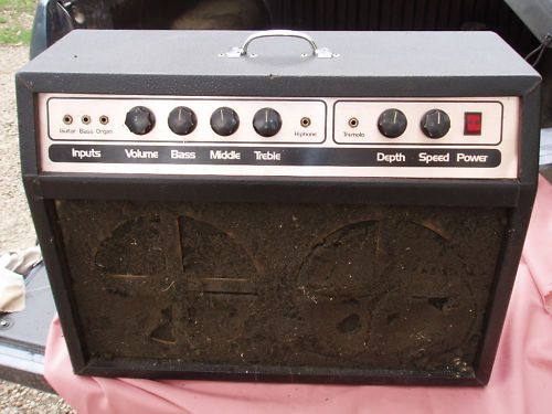
Another possible Savage.
Source: Dennis, e-Bay spotter
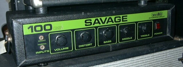
Savage is included here because it is of similar vintage to many of these valve amps, but mainly because I saw one in Cash Converters the other day (June '04) and was amazed that any had survived at all. The “85” was typical of the numbers race that was going on at the time, and nothing to do with watts RMS.
They kindly let me take a pic;
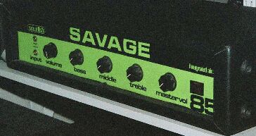 Cash Converters Smith St Melb. July 2004 Black front panel with green silk-screen overlay (orange for bass). Large black Sato knobs. Power: (claim) 85 watts into 4 ohms Line and distortion sockets on the rear Serial: 673 149 Asking: $A399 Front panel bent inwards. Service sticker: Aeriel Amplifiers
[Aug '05 it's still there, now marked down to $199, and still far too expensive. The only future for this amp is stripping and a total solid-state rebuild, so the tranny, chassis and case are worth about $100]
The name Savage sticks in my mind because they had to be the worst horror show I ever had the misery to deal with, and in bulk. There is nothing quite so depressing to a tech as an amplifier where repairs won't stick; where it blows up again under test.
The basic problem was that the manufacturer had simply ignored the maximum voltage ratings of all the transistors they used and major blow-ups under normal conditions were certain and frequent.
When they let go they literally vaporised just about every transistor in the amp, leaving blacked circles of char and the remains of melted leads where they once had been. A truly ugly sight.
You think I exaggerate?
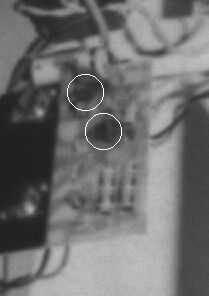
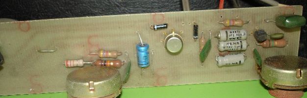
This one is a later encounter c1975, only mildly blown up, bombsites circled.
Note the pathetic “heatsink”, expected to get rid of 40-odd watts.I heavily modified about five of these for a friend who owned a music shop and who had been unfortunate enough to be impressed by their looks and price.
After the mods they made only 60 watts, but at least they would do it all night without smoke.
If ever there was an amp to give transistors a bad name and confirm a love of valves, Savage has to be it. Looks very imposing but the design is inherently unreliable in its original form, and didn't sound that great either.
It's not just guitar amps. I've met gear across the board that has been improperly designed for its job. These always have unhappy endings because the owner always transfers responsibility for the basic design defects to the repairer. On the bench a simple repair job turns into a design nightmare as you try to make a sows' ear work properly. After a number of brusing encounters this is one of a few amp names I would refuse as a repair.
Avoid. Or gut it and put your own dreams in the seviceable chassis and case.
July '04
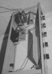
I have been reminded by another tech who had bitter experience of these that they had a serious cooling problem too.The initial run had what became a fairly common construction with the power transistors on an 'L'-bracket to the chassis rear wall. The rest of the amp was on a PCB also mounted on the 'L'-bracket, typical of many kit amplifiers since.
The problem was the chassis was steel with a thick coat of black paint on it. It's true that black radiates better than white, but paint itself is a fairly poor thermal conductor. Worse, a steel chassis is a futile imitation of a heatsink because of its very poor thermal conductivity.
Later versions mounted the 'L' off the chassis inside on standoffs, but this hardly changed the thermal situation. The L-bracket was still too thin and the heat still couldn't get out.
New: 7/10/07
Anthony “Asynchronous” writes of his encounter with S.No: 673 143;
Anyhow, the guitarist in my band gave me his guitar amp to fix, and sure enough, it's a Savage 85. This is the first I've seen of it, because he used to hire an amp and now uses one of my guitar amps. He told me that he doesn't use it anymore because 'something' went and his pop bypassed the 'something' because the part was no longer available -to which I thought, hmmm...
Some searching of the net revealed that there's no info on this amp other than your website, and after reading you postings on your experience with this amp I figure you may be able to at least give me some pointers. Actually when I saw the serial number you listed I freaked out and thought it's the same amp, but the amp I have here has s/n "673 143". The good news is that if you want detailed photos in and out and schems of this amp I can contribute..if you do want them that is [INSERT SMILING EMOTICON HERE].
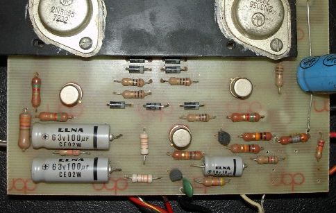
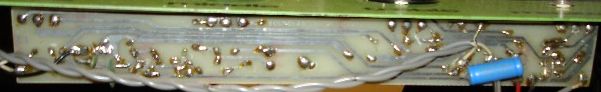
Main power amp topside
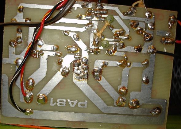
Main power amp copper side
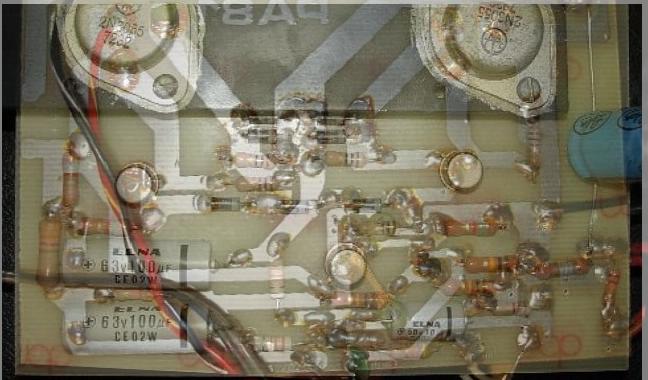
“X-Ray” viewEarly preamp left end
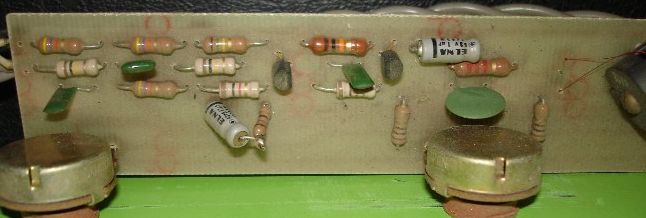
Early preamp right end
Notes: the lead from the distortion socket on the rear arrives here to the vacinity of the two diodes.
And that looks 'orribly like a 709 (or 741) op-amp that could well be replaced with something a whole lot more modern, quieter, less distortion, more bandwidth, and actually intended for audio - such as one of the TL-07x series.Early preamp copper side
New: 3/7/06
Source: Ric's Vintage Guitars, Perth
This marque of amps, as built, has a lot of problems, mainly with the power output amplifier at the design stage. A number of things were neglected, and these provide a good set of object examples that illustrate how to do it properly. These mods have different levels of urgency, from keeping the amp working at all, being roadable reliable, defensive, to non-critical improvements. But, as you will see, there is a lot to be put right.
The following comments are specific to the early, unmodified, "85" units, but no doubt applies to other models in the line because any “designer” who thinks they can screw 85 watts RMS out of a pair of 2N3055's is obviously several tiles short of a roof.
This amp represents an exercise in optimalism - “what could possibly go wrong?” Well, the designer who chose components either ignorant of their datasheet specifications, or cherry-picked the most favorable numbers - that's what.
Meanwhile, out in the real world, designers whos' gear actually works, delivers the goods day and night despite constant abuse, concentrate on the worse case sceanarios, and have Edsel Murphy's immortal words written in their hats - “If something can go wrong, it will”. Electronics in general, and band gear in particular, is full of nasty surprises for the optomistic.
Credit must go to Douglas Sargent and Anthony “Asynchronous” for e-mails that inspired the following.
Contains: * What have we got? - initial circuit
- Power Supply
- The output stage - transistor types
- Cooling - how to get some
- Emitter resistors - survival mod
- Output coupling cap
- Output stability
- Inductor/resistor
- Zobel network
- DC return - the burned resistor
* Drivers
- Bias and thermal stability
* The modified circuit
* Heatsink tips
What have we got?
The power supply is a very simple bridge-rectified single-rail type producing about 70 to 75 volts of DC. The primary side has a mains fuse and mains switch with in-built neon power indicator.
The output stage is a quasi-complimentary where a totem-pole pair of NPN transistors are driven by a complimentary pair of NPN/PNP transistors. In this case the amplifier output is coupled to the speaker via an electrolytic capacitor.
“Quasi-complimentary” means that the output transistors are of the same type, here NPN, and that a real complimentary NPN/PNP pair are used in the driver stage, in theory effectively making a complimentary pair of output transistors.
In actuality this results in upper and lower output “cells” that have every different gains which cause great consternation to the Hi-Fi crowd. As a result you will encounter two major variations of the fully-complimentary amplifer, one where the NPN/PNP output pair both have their emitters to the half-rail, and another arrangement where both collectors go to the half rail. The idea is to equalise the cell gain. In the first case both cells are emitter-followers, and in the second, both have gain.
A healthy power amplifier will bias its half-rail, or output line, to half the supply voltage, or around 35 to 37 volts in this case. A half-rail stuck near ground or supply is a certain sign of problems.
There's nothing much inherently wrong with this general quasi-comp arrangement (in fact my own Twin-50 keyboard amp is similar) - if, like any amp, it's done properly.
Power Supply
The power supply can be safely ignored for the moment as “satisfactory”, but its simplicity, against a dual-rail supply, forces the use of an output coupling capacitor. We'll get back to this.
The output stage
The major problem these had in service was that the driver transistors had insufficient voltage rating, and they would evaporate.
When in doubt I reach for a BD139 or BD140. I have a similar board entirely populated with them from input to driver. They may not be optimum but they seem to work just fine in all areas.
BD139 NPN
Case: TO_126
Pmax: 8W
Vcmax: 80V
Icmax: 1.5A
hfe: 63/250 @ 150mA
(ZT-2189 $0.85* e.g. Jaycar '07/8)

BD140 PNP
identical spec
(ZT-2140 $0.85*)
The TO-126 is a small plastic flatpack with a mounting hole through it. The back has a metal face connected to the collector.
The 2N3055 output transistors seem to serve okay, but they have pretty unimpressive specs compared to some of the transistors available today. They have a particularly poor power-bandwidth, and you can encounter problems even in the upper audio spectrum where they can be quite lossy and inefficient.
2N3055
Case: TO-3 kite
Pmax: 115W
Vcmax: 60V
Icmax: 15A
hfe: 20/70 @ 4.0A
(ZT-2300 $1.75* e.g. Jaycar '07/8)
Of particular note here is that the current gain, hfe, is down to around only 20 by the time the collector current, Ic, is up to 4 amps. This loss of hfe continues with rising Ic and is a major reason not to design for Ic in excess of about 4.5-5 amps.
Of secondary note is that the Vc (strictly Vcbr) rating is with a low impedance (100-470r) between the transistor base and emitter to shunt any CB leakage. With it open (Vcbo) the rating is only around 40 volts, and this amp is already stretching the friendship with the Vcmax rating of 60 volts.
Just on the specs the MJ15003 looks like a superior replacement.
Note that the MJE3055 comes in a TO-220 large flatpack. This is a very useful transistor in its own right, but don't be fooled by the “3055” tag - it's similar, but its critical ratings are much lower than a TO-3 2N3055 and cannot be substitued in most amps. Also watch out for a power FET, itself an almost ideal interface from logic to power, which also has “3055” in its number but is again unsuitable here.
Cooling
A central problem with the Savage is cooling. No transistor is going to survive being left to stew in its own juices, and these amps originally didn't have any heatsinking worthy of the name. This is a major and critical problem.
A heat sink is not something magical that soaks up heat like a sponge. It's a coupler that is intended to thermally couple the chips of your devices to the surrounding air. We'll come back to this.
A solid-state amp with pretentions to “85 watts RMS” needs to have a very serious heatsink, since a roughly equal amount of power is going to be wasted in the output stage.
The main problems with retro-fitting a much bigger heatsink is twofold; how to get the heat through the steel case (hopefully without having to resort to gas-axe, angle-grinder and tin-opener); and where to fit the heatsink since there is very little depth available on the rear.
You could get away with putting it inside, provided you blow it and the case with a fan (thermally-controlled).
Emitter resistors - survival mod
For reasons perhaps only known to the designer, they elected to use paralleled forward-biassed power diodes instead of the conventional emitter resistors. Wrong!
In itself, paralleling silicon power diodes is an idea which has practical problems in that one diode tends to try and “hog” the current instead of sharing it, as is the intent.
These four diodes and the fractional-ohm resistors that shunt them, should be removed and replaced with two 0r22 ohm 5 watt power resistors.
Why? These resistors are a major source of thermal stability for the output transistors. Using diodes would certainly maximise power, but at the expense of thermal stability and possible thermal runaway. It's like clamping down the emergency relief valve on a boiler.
Thanks to work done by Doug Self we know that 0r22 is close to the optimum value for just about every case.
With semiconductors, the conduction threshold, Vgamma, falls with rising temperature, as a result as the amp get hotter the output transistors will be turned on harder, making them even hotter. Resistors do exactly the opposite, counteracting any change in the current from the bias setpoint. Note that thermal circuits can be understood is electrical terms such a Ohm's Law and feedback loop dynamics and can also thermally stable or unstable, even oscillate.
We will return to considering thermal stability when we look at the bias arrangement, below.
Output coupling cap
I'm still amazed that a puny output coupling cap like the one used (l.blue cylinder, right), hasn't exploded more often.
The output coupling cap is only exposed to a voltage half that of the supply. Normally.
Caps are rated in capacitance in microfarads, maximum working voltage, and the lesser-known ripple-current rating arising from the losses in the cap.
So, how much AC current is this capacitor being asked to carry?
watts=85
ohms=4
amps=Sqrt(watts/ohms)
	amps = 4.610
Pkamps=amps*Sqrt(2)
	Pkamps = 6.519
So we have an average output current getting on for five amps, and the peak current is a whopping six and a half amps! Is it any wonder most speaker connectors aren't up to it. Also, for sundry reasons, the 2N3055 has a practical upper limit on its collector current, Ic, of around five amps (see above), and is happier with the 50/60 watts into 8 ohms condition.
watts=60
	watts = 60
ohms=8
	ohms = 8
amps=Sqrt(watts/ohms)
	amps = 2.739
Pkamps=amps*Sqrt(2)
	Pkamps = 3.873
And all that AC current is flowing through the output coupling capacitor.
Normally speaking the voltage rating only has to be half the supply, but one day the upper transistor will short and it will be subjected to the full supply voltage. If it then fails, it takes your speakers, and the amp power supply, with it.
So a logical choice would be a big can-mount such as the 4000uF/75V (Jaycar RU-6708) with a ripple current of 4.6 amps.
Output stability
The burned resistor in the picture above (rh-side) is the DC return resistor across the output, and it being burnt is a symptom of an amplifier that is suffering supersonic instability. This tends to give both the speaker, tweeters in particular, and the amp quite a hard time by driving them continuously, even if inaudable. It also degrades the signals you can hear.
There are two types of high frequency unstability, supersonic, and VHF/radio frequency.
Inductor/resistor
In many amps there is an inductor (coil) in series with the output. This addresses supersonic instability by isolating any capacitive element in the load, such as a tweeter, from the output stage.
As you can see from the various amp designs around, this little coil can vary quite a bit, so it isn't all that critical. You could just copy and install a heavy-guage coil.
Or more simply you could fit another 0r22 ohm 5 watt wire-wound resistor in series with the output, right at the output on the printed board, before the coupling cap.
Zobel network
For a network with only a resistor and a capacitor, the poor old Zobel network has to be the most mis-understood in electronics (and I am indebted to solid-state amp guru Doug Self).
The Zobel network is simply a resistor and capacitor in series, typically 47 ohms 5 watt and an 0.1uF cap of 100 volts or more, connected between the amp half-rail and ground. The function of this network is to prevent local HF or VHF self-oscillation around the output transistors, and therefore be wired in VHF-style, short leads, right on the output, and on the amp side of any output inductor/resistor.
DC return
The dreaded burnt resistor.
The output coupling capacitor needs somewhere to charge up from in case the speakers aren't connected. This helps to prevent an almighty splat when you plug the speakers in after turning the amp on. It happens. Another 100r/5 watt across the speaker socket will fix this.
Drivers
If we now take a look at the network on the bases of the driver transistors, we see an odd arrangement of resistors, a capacitor, and several apparently wasted diodes in series. (The stage that drives this does so by drawing current out of the bottom “Drive” point - something like another transistor to ground).
Bias
You could leave this unbiassed, but the crossover distortion would be horrible. So this has to be biased out.
There are several ways this can be done.
Left-to-right; Vbias due to (a) due to a current through a resistor, (b) two diode Vgammas,
(c) amplified EB, or (d) two EB's as in (b).
Because each of the transistors requires an initial voltage of around 0.65V (650mV) on its base before it starts to conduct, and because we have several such junctions stacked up through the power amp, and because we want the whole totem pole to be slightly in conduction - we have to bias the drivers.
In simple terms we have one diode drop in the upper 2N3055, and another in its driver, and the lower cell is represented by the single drop of its driver EB junction. So we have a total of three diode drops, hence we see three bias diodes in series. In theory these cancel out the drops in the drivers and output, putting it on the brink of conduction.
Now we return to the fact that these voltages in silicon semiconductors have a temperature co-efficient of about minus-2mV per degree C. We have two sets of three junctions in parallel - and we already know that this is an unstable situation.
So the normal thing is to arrange for two of these bias diodes to be thermally coupled to the output transistors/heatsink. You can get away with leaving them on the main PCB in a cheap domestic stereo, but gigging amps can get very hot, so knowing a solid-state amp is thermally stable is important.
And while normal diodes may be cheap, they are not the best answer to this problem. The chip or dice is very different to a transistor and thus doesn't track very well, and worse, the cylindrical physical case is difficult to keep thermally coupled to the output transistors.
Transistors as diodes
Again the BD139 or BD140 provides a nice answer (whichever you have an excess of, just watch the polarity).
If you use the EB diode, (you can tie collector and base together), and you apply heat, you find that;
- the diode voltage tracks well,
- unexpectedly it's more thermally responsive on the top of the case than the metal flange,
- and the package with the hole is much easier to mount firmly. With some 2N3055's you can even get them against the flange end on a common mounting bolt.
These should be mounted using thermal grease, topside against the heat source to be monitored, metal flange up and insulated, with suitably insulated and sleeved flying leads back to the diode positions. These should be near where they have to connect to the circuit to minimise lead length, but also in proximity to each output transistor for tight thermal coupling.
To measure thermal stability...
...you need;
- a means of measuring heatsink temperature (such as DVM with thermocouple probe)
- a dummy load
- a means of measuring current
First, run the amp at idle and monitor the voltage across one of the power transistor emitter resistors.
There are three possible situations;
- the voltage will quickly settle to the value set by the bias, and remains utterly stable.
- the voltage will eventually get to around the desired value, but may vary erratically up and down, more or less, over time - quasi-stable.
- or it may vary up and down in a clearly regular oscillation, even going into thermal runaway - un-stable.
If the amp appears to be stable when idle, then use a sine signal source and dummy load/wattmeter to run the amp at ten watt increments for at least 30 minutes each, observing that the heatsink temperature is still stable, and between runs quickly measuring the hot idle current, as above.
It may be under-compensating, then the idle current will rise with temperature, correct, or over-compensating, when the idle current is reduced too much at high temperatures resulting in excessive crossover distortion with a hot amp.
As a guide, I have found that using all three transistors-for-diodes results in over-compensation, while changing only one is insufficient.
The modified circuit
errata: connect C-B'sCalculations in the section done using SpeQ Matematics.
If you are confronted with a problem like this:
- Heatsinks need to be bigger than you think
- A heatsink is a coupler not a black hole
- The heat/hot air has to escape somewhere or it will accumulate
- Cool air has to come in from somewhere
- Air friction requires large openings (but screen against insects, rodents and fingers)
- Lay out for good convection cooling before adding a fan
- Fans deliver 90% of their cooling in the first 10% of their rev range
- Thermal control of fans for noise abatement is simple these days
|
|