http://www.ozvalveamps.org/testgear.html | Created: 2006-07-07 | Last update:
20:10 24/08/2013
<<< OzValveAmps
|
Test Gear
You can test a 9 volt battery by sticking it on your tongue.
But for testing valve amplifiers some other equipment is useful.
Valve amp collectors also tend to be drawn to classic period test equipment that uses valves, so here we look at some of the considerations in repairing, renewing, re-calibrating, and using such gear. I assume you already know your way around the insides of a valve amp, but are new to test instruments.
Contains:
|
Introduction | Meters - Vacuume Tube Voltmeters (VTVM), Meggers | Audio Signal Generators, Phase Shift, Wien Bridge, Twin-T, Beat Frequency Oscillators | Cathode Ray Oscilloscopes - CRO's, CRT's, Attenuators and Amps, Timebases - gas, Heath, Miller, Puckle
|
Introduction
We can't know electricity by direct observation. We require instruments or “test gear” to translate what we want to know into a form we can see.
Since these indications are the only thing we can base our reasoning on it is important that they do not mislead. As all instruments have their limitations it is important to know the limitations of your own particular set of instruments so you can allow for them in your reasoning.
Apart from restoration and repair, it is valuable to know something of how your instruments do what they do, so you can guard yourself from being misled by their errors, and they are all capable of giving misleading readings in particular situations.
Vacuume Tube Volt Meter - VTVM
Meter amplifier.
Early moving coil meters were insensistive, say typically 1ma full scale, and valves were used quite early to amplify and buffer the meter movement.
In bench form these were initially called VTVM's because they didn't have ranges other than AC and DC volts. While they grew resistance ranges to compete with VOM's, I can't remember ever seeing a VTVM with current ranges.
By the end of WW-II the design had stabilised to the extent that there was very little difference between different makes. As with many instruments of the era the range switches are typically of special construction, making repair the only real option.
The heart of a VTVM is the double triode, typically a 12AU7, that forms a bridge circuit with its cathode resistors (R34, R35). A meter is connected, in series with a calibration pot, between the cathodes.

Note the custom switch wafer selecting the calibration
Note the very high values of R24 3M3ohms and R32 10Mohms. The resistors used were generally metal film and not prone to drifting, but after a few decades all components, especially high value resistors, must be suspect.
That said, the most common problems are those you would expect, dirty switch contacts; damage or magnetic filings in the meter movement; and finally the valves worn out.
Typically a VTVM has a basic sensitivity or lowest range of 1.5 volts FSD, meters for signals lower than this are generally called “Millivoltmeters” rather than VTVM's, and their sensitivity control will be oriented to -10dB steps rather than the 1,2,5,10 sequence.
These DC amps need longer to warm up and settle than an audio amplifier, about 5 to 10 minutes, and a manual DC balance control allows you to correct for drift before each measurement. Some wild meter movements in the first minute of so of warm-up are normal. Later FET-based FVM's normally settle much more quickly and have much better long-term stability, and use very similar circuits.
This balance control can also be used to set the pointer to the calibration at mid-scale for center-zero operation, such as aligning an FM demodulator. If you do offset the zero for any reason take care that the amp will again need to settle for a minute of so before taking the first measurement.
You will also often find the function switch has positions for “DC+” and “DC-” since it is not a good idea to clip the common to the minus 1200 volt supply in your CRO to measure it as this will generally test the insulation of the VTVM power tranny.
Range selection - input resistance
This differential cathode-follower amp (above) is preceeded by a switched attenuator containing some rather odd resistor values. This is generally arranged to add up to 10 megohms across the attenuator, and a single 1M resistor in the probe itself, giving a total input resistance of 11 megohms.
More on VTVM's in a moment, but first a little rewind for some related background. . .
VOM's - multimeters
New: 23/10/09
In a conventional moving coil multimeter or VOM the input resistance changes with different ranges, hence the input is given as “X ohms per volt” (more is better), implicitly the set voltage range. The two most common are cheap 1k/V or 1mA, mainly useful for car electrics because they are not safe on high voltage nor sensitive enough for electronics; and 50k/V or 20uA which normally are suitable. On the 1V range it would have a resistance of 50k ohms while on the 1000V range it would be 50k x1000 = 50Meg.
This is the current drawn from the circuit under test for Full Scale Deflection of the meter. Normally this isn't a problem, but in some cases, such as measuring the anode voltage of a preamp stage, your meter will draw sufficient current to pull the reading down significantly on the actual voltage. In such cases readings should be taken on the highest practical range setting.
Test equipment loading
Let's take a real guitar amp example, measuring the anode voltage on a typical triode preamp stage with 300.0V HT and 220k anode load, biased for the mid-point Va=150.0V using a 50k/V meter set to a 200V range.
The resistance of the stage can be considered to be two 220k resistors in series across 300V, and we are connecting our meter in parallel with the lower or earthy end resistor (i.e. the valve).
Before we connect our meter there is a current E/R;
300.0 / (2x 220k) = 682uA
On the 200V range our 50k/V meter has a resistance of;
50 x 200 = 10 Megs
When connected in parallel with the lower leg the resistance becomes;
(220 x 10000) / (220 + 10000)k = 215.26k
Now the total current is;
300.0 /(220 + 215.26) = 689uA
The voltage drop in the anode load resistor is now;
220 x 0.689 = 151.58 volts
The actual voltage is 150.0 volts, while the reading will be;
300 - 151.58 = 148.42 or about two volts low.
In the much higher resistance grid circuits the effects of test equipment loading can be very significant.
|
DMM's - Digital Multimeters
Dig out the little book that came with your $9.99 Yellow DMM and look up the specifications page.
I take as my example the slightly up-market Digitor Q-1467.
The good news is that the input resistance is 10Mohms for all ranges, well, except the AC ranges where it is only 5Mohms, but that's pretty good.
The worst resolution on the highest DC range is 0.8% plus 2 digits. You have to watch that rider because sometimes the digits error swamp the basic conversion error. So when we look across at the AC error of 1.2% we see it is swamped by a massive 10 digit reading error, i.e. the Least Significant Digit is meaningless, that for AC at least, it's a 2 and 1/2 digit meter.
In the context of valve guitar amps the quoted AC bandwidth is significantly limited at 40-400Hz, and test results on bass amps below 50Hz must be suspect. So while your DMM can give you “useful indications”, it is no way an audio voltmeter like a VTVM or proper audio millivoltmeter.
DMM's have one serious “gotcha”. If you probe AC, such as the mains, with a moving coil multimeter accidentally set to a DC range the pointer will vibrate furiously around zero. It's very characteristic and can even make a warning buzzing noise. No, it isn't kind to the meter, but who is more important here, you, or the meter?
Make the same mistake with a DMM and you get a very different, and ambiguous, response. DMM's normally dribble around zero, and that's sorta what you get, but if you observe, the values will seem to be cycling around zero, jumping around more than normal with occasional high-ish values. Watch for this folks because it is a sign that there is AC where you are expecting DC, and it might be the last warning you will get that you are unintentionally probing the mains.
Addendum 24/08/2013
Two points arising; really cheap DMM's have an input resistance of only one megohm which will produce serious loading effects around valve circuits; and on the AC ranges they are not isolated from DC meaning that any attempt to read AC in the presence of DC, such as trying to measure ripple on the HT rail, will produce seriously odd results (a DC blocking cap of around 0.1uF with a suitable voltage rating must be used).
Unlike a normal moving coil multimeter . . .
the input resistance of a VTVM is a constant 11Meg irrespective of the range setting.
The AC side is taken care of with a double diode, typically a 6AL5.
The AC side generally has an input resistance one-tenth of the DC input, around 1M1. As with all AC meters the input impedance will fall somewhat with rising frequency, but they tend to have better bandwidth for audio work than VOM rectifiers.

Input via C2, output lower left, balance tickle top right via 4x 22Meg
It may have, as in this case, an AC Balance control. This feeds a tickle of power mains frequency into the rectifier to cancel out any hum pickup. This is set so there is no difference between probes shorted and open on the lowest AC range.
The HT supply is often 120-150 volts or so, but may be grounded at some mid-point producing a lower voltage on the anodes and an apparent negative supply for the cathodes.
One point to remember is that these are still basically moving-coil meters and can suffer all the same ills, tangled springs, magnetic crud in the gap making it sticky, or the pointer touching the scale.
A meter can be given a crude test by holding it horizontal and giving it a quick left turn. The pointer should be left behind and go smoothly part way up scale and return smoothly. Many common meter problems are easy to fix with non-magnetic tools, a big magnifier, lots of light, and a very steady hand.
These days it's more common to come across just the meter itself recovered from some VTVM in a junk shop or garage sale. A bare ex-VTVM meter can be quite impressive, anything up to 6 inch by 8 inch scale, multiple scales, and perhaps a mirror strip for anti-paralax reading. If it's sticky, haggle hard. But such a meter would make a great start on a VTVM or FET-VM build.
Full circuit for Heathkit VTVM model IM-1.
Megger
“Megger” is actually a particular brand name of a electrician's megohm-meter or high voltage tester, but it was obviously such a popular model the name has stuck as a generic, like “Hoovering” the carpet or “Leslie” speakers.
Meggers are basically ohmmeters and so have meters too, but somewhat different in that they force-balance and often don't have return springs. This means the pointer tends to flop about when it isn't in use, giving a mistaken impression of being busted. A gentle rock should be enough to send the pointer end-to-end and show any sticking.
Modern “Meggers” have batteries and high voltage inverters, but the real thing has a crank handle, gearbox, and a dynamo inside. This turns out to be really handy for bringing the voltage up gently on a suspect HT line, or crank it hard for a full 600 volts insulation test. The scale normally starts about a 100k or so and climbs through 100's of megs to infinity.


A cap charged to 600 volts using a Megger is still charged to 600 volts! The Megger alone may give you an interesting tingle, but the charge stored in a capacitor will really make you jump.
The HT line of a cold amplifier charged up in this way may have no ready way to discharge again other than leakage unless you provide it. It is not good practice to discharge power supply caps by simply shorting them, and is a risky habit if you happen to service higher power amps, particularly solid state ones where the return of energy can be dangerously explosive. Use a suitable resistor, or your trusty mains lamp gimmic.
Many Megger-type instruments also have an ultra-low ohms range for testing earth wire resistance and the like, so a megger will serve for resistances both above and below the ranges on the typical VOM.
A very handy tool around old valve amps when testing and reconditioning.
But use with caution testing house wiring as these days there are some devices such as light dimmers and downlighting “solid-state transformers”, actually switch-mode power supplies, that may be damaged by a megger.
Audio Signal Generators
These come in a number of different types such as, Phase Shift, Wien Bridge, and Beat Frequency.
Phase Shift
The Oscillator we are most used to is the phase-shift oscillator typically found in guitar amp tremolo circuits.
The only real drawback with using this method for a wide range oscillator is that three capacitors have to be switched for ranges, and three resistors have to be varied for the frequency tuning. It is possible however to tune a PSN with only one variable resistor if you aren't too worried about other factors such as wave purity.

Source: E.N Bradley (1)
Because of losses in the PSN the amplifier requires a gain of around 30 to oscillate.
PS oscillators tend to have good frequency stability because they have a fairly high rate of network phase rotation around the tuned frequency.
The PS oscillator can be made using either the typical high-pass network with the capacitors in series, or the rarer low-pass network with the resistors in series.
The frequency for a three rung ladder is determined by;
f = 1 / ( 2 Pi R C root(6) )
A four-rung version can be used if quadrature outputs are desired.
You can find more detail on Phase Shift oscillators at Aitkin Amps.
Wien Bridge
By far the most common arrangement used in bench audio signal generators is the Wien bridge. This does a similar feedback trick as the PSN above, but with only two caps and two resistors, reducing component count and range switch and frequency pot complexity and cost.
R and C form the Wien lead-lag network that determines the frequency, while the feedback network of resistor 2R' and thermistor R' set the gain to around three.
The frequency is given by:
f = 1 / ( 2 Pi R C )
Wien bridge oscillators tend to have a fairly poor frequency stability because the rate of phase rotation around the tuned frequency is quite slow. This is the bandpass:
Twin (or Bridged)-T)
Another frequency-selective network that can be used is the Twin-T arrangement. Because this is a nulling network it is more often found in Noise and Distortion meters, NAD's, where it is used to cancel out the test signal leaving only the distortion products to be measured.
Since these distortion products may be originating in your signal source it is desirable to get your test oscillator as clean as possible. The amps you work on can only be as good as your instruments, and it's a whole other demanding challenge to get your instruments working ten times better.
The network frequency is given by:
f = 1 / ( 2 Pi R C )
Twin-T networks have a very high rate of phase rotation around their tuned frequency and therefore tend to be very frequency-stable.
One of the very many Heathkit instruments you may encounter. This is an audio generator model AG-9 which is built around a Twin-T network.
Beat Frequency
Audio BFO's are pretty rare animals. They are generally large, have a dial that goes right down to 0 (zero) cycles per second (Hertzes), and may have something like an electron-ray or “magic eye” tube near a cal or trim adjustment.
These are actually two oscillators, both moderately high frequency, say around 1MHz. One is fixed and may be quartz-crystal locked. The other is a VFO tuned by a large variable capacitor.

A Colpitts LC VFO
The audio output is the beat note of the offset or difference between them, hence the ability to actually go to zero Hertz. This sort of oscillator normally has a quite pure and undistorted output, and good amplitude stability when swept, but fairly average frequency stabilty.
The output of the two oscillators go to a mixer stage, then a low-pass filter and output amplifier and attenuator.
The function of the magic-eye to to show zero beat and when the dial is set for zero Hertz the cal or trim control is used to stop the eye fluttering, making the output conform to the dial reading.
Another advantage of the BFO is that the entire audio spectrum can be covered in a single sweep of the dial and I've seen up-market generators of this type fitted with mechanical sockets for a Bowden cable (speedo cable) to synchronise a chart recorder for bandwith plotting.
LC
If you're really nuts you can build an audio oscillator using an inductor and capacitor to tune it. I've actually built valve LC oscillators that ran at only 10kHz, and I'm sure you could go lower, but the coil and variable cap required get physically quite large so this type is generally only used in RF signal generators. They are potentially capable of very pure output waveshape.
In general
The most common problem with an old audio generator is that it lights up just fine, but won't oscillate, or only at one end of the dial, or only if the dial or range switch is disturbed, then the oscillation will die away.
Failure to oscillate is lack of loop gain; either the amp is no longer giving the required voltage gain to overcome the network losses, or the losses in the network have gone up due to a dodgy component.
The amp should demonstrate a significant voltage gain between input and output. If you don't have reasonable gain look to the amplifier. If you seem to have sufficient gain then look to the tuning components. Dirty or broken range switches are a common cause of problems.
In older sig gens the amplitude was normally stabilised using a carefully chosen filament lamp, often soldered in place somewhere under the chassis. This should last forever since it hardly lights at all, but the filament is fragile and could have been knocked open circuit.
This lamp is often in series with the cathode bypass capacitor, and as it is heated by AC flowing through the bypass it increases its resistance by several times, introducing some local negative feedback and cooling the oscillation. It may be found in other parts of the circuit but the principle remains the same.
The selection of a replacement is basically cut and try, looking first for reliable oscillation for all range and frequency settings, then at the settling time of the output when the tuning is altered. For lowest distortion you want the lightest possible oscillation that will still work for all settings.
Conflicting requirements are a fine filament with low mass and thermal inertia for quick response, but at some low frequency the lamp starts to react to the low frequency oscillation itself as amplitude variations and starts to distort the wave. The lamp can also be sensitive to heat radiated from nearby.
Squegging, bursts of hard oscillation that switch on and off, are a sure sign of too much loop gain and oscillation at two frequencies at once.
There is always a trade-off between settling time and output distortion. You may have to accept a long settling time if you want good output purity, or some distortion if you want amplitude stability when sweeping.
Mainly its the same old stuff, noisy pots, dirty switches, dried-out electrolytic caps, resistors drifted high (or low), weak bottles. Sometimes it's abuse such as boofed front ends or tangled meter hair springs due to a drop. And sometimes it was simply displaced by a newer instrument and only needs a tidy-up.
If you find an audio generator with a meter for the output level you will often find it is driven by a circuit similar to the VTVM, above.
Cathode Ray Oscilloscopes - CRO's
This section assumes you already know a bit about valve amps, and concentrates on the elements you won't find in a guitar amp.
For CRO basics, how they work and how to use one, please see CRO links.
If you want to repair an old CRO, or build one, read on...
The Cathode Ray Oscilloscope has always been my first love in electronics. I was reading about them before I was safe with a soldering iron or high voltage, but they have held a compelling attraction for me ever since I saw my first one.
Apart from being very useful around the workshop, particularly with any kind of developmental work, the spot on the CRT screen is about as close as you will ever get to actually seeing electricity.
I had one of these 905's going on the bench for a time c1970 until a tranny fell on it (and I almost committed matricide). It's a rather odd feeling when you look at the screen from behind where the electron beam is striking it.
Phosphors and PDA's
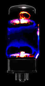
As we know from power valves, electrons striking the envelope can cause a pale blue glow in the glass.
In this KT88 it looks like electrons that have been emitted from the exposed top and bottom sections of cathode are curling around the end structure heading for the outside of the anode. Those electrons taking a wider path strike the glass, causing minerals in it to emit blue photons as secondary radiation.
It isn't the Large Hadron Collider, but it is your home sub-atomic particle accelerator.
The inside of CRT screens are coated with a thin layer of material called a phosphor which glows very strongly when hit by electrons. (Why they do this is a whole other interesting story, but it's basically a case of greatly enhanced secondary emission.)
The phosphors themselves are compounds of various materials including Rare Earths and mildly radioactive materials.
While these materials pose no danger while inside an intact CRT a broken tube must be treated with extreme respect as a serious toxic/radiological hazard, a wise policy with all valves actually. Take the greatest care not to ingest, inhale, or get the dust in a cut. Incidentially this is also true of common flourecent lighting tubes of all sorts (which also contain a mercury hazard). Have fun, but play safe.
Phosphors may not be safe for children but they certainly come in all the colours of the rainbow.
The main types of phosphors normally encountered are the red-yellow group, the green group, and the blue group.
The red group are normally found in radar equipment because they have the longest persistance and continue to glow for 100's of milliseconds out to 10's of seconds depending on the precise mix and application. These are most often seen as radar PPI's with a line sweeping radially around the screen mapping the surroundings in bright orange.
The green group are the most common found in everyday oscillography with a short-medium persistance around 1-10mS.
The blue group are fairly special and mainly intended for photographic applications with a short to very short persistance where the spot leaves very little comet-tail afterglow.
One interesting exception was a tube used in a Cossor (UK) which had all of these groups represented in one tube. The result was a white spot that left a tail that changed colour with time. This was more than a sexy look (and it did look very sexy).
The CRO came with a set of matching coloured graticules that allowed the user to select the desired persistance by dropping in one of these filter-graticules; effectively a variable persistance CRO! Blue for photographic, green for general, and red for slow stuff.
The phosphor glow effect is enhanced by accelerating the electrons using high to very high voltages, from about 1 to 5KV in conventional CRO's and as much as 25KV in fancier tubes.
Tubes with a Post Deflection Accelerator can be recognised by having a connection (such as a ball-head stud in a little well) up near the screen somewhere, and there may be a fine spiral visible inside the tube glass running back towards the base end.
Primitive PDA tubes just had another electrode between the gun and the screen, generally in the form of an internal “Aquadag” conductive coating. In better tubes this is cut into a spiral to form a long very high resistance electrode connected back to the base.
The effect is to form an electrostatic ski-jump that accelerates the electrons very considerably. This gives a very bright and tight spot and reduces sensitivity to stray deflections such as hum field from the power tranny.
It is applied after deflection because the deflection sensitivity of a CRO tube falls as the final anode voltage rises, so a compromise normally has to be struck between sensitivity and a sharp image. The PDA allows both high sensitivity and a sharp image.
Bringing the end of the spiral out allows it to be used as the voltage divider for the EHT voltage regulator sense and feedback, giving very stable overall tube operation.
Sometimes you may find a coil wrapped around the neck of a CRO tube, connected to a variable DC source. This is the twist coil and set to correct for the remaining slight axis misalignment between the deflection plates in the gun, and the graticule on an integral-graticule tube such as found in up-market CRO's.
These should not be confused the the auxillary magnetic deflection coils fitted to some Cossor models, or with rotating scan coil assemblies found on some old radar tubes.
Take great care handling CRO tubes. They are rare, valuable, and large glass containers under hard vacuume which will implode if fractured. This can have much the same effect as if they had ex-ploded, spraying broken glass in all directions, particularly in larger CRT's. Wear eye protection when handling. All mountings must be padded, no metal-to-glass contact. Don't over tighten mountings.
CRO tubes are often fitted with a magnetic shield due to their sensitivity to stray magnetic fields. In better gear these are mu-metal and should also be treated like glass as their magnetic properties will be ruined by dropping, hammering, drilling, etc. Also keep them away from stray magnetic fields such as speaker magnets and energised power transformers. In one of my early builds I used a short length of what looked like heavy-wall scoffolding tube internally padded to hold a 3AP1.
In my mis-spent youth there was a store in Elizabeth St Melbourne called Waltham Trading, an “army disposals” store which sold a wonderious range of old junk including the most mouth-watering collection of CRT's.
$3.50 would get you a 3-inch 3AP1 or 3BP1, 5BP1's for a buck an inch, and 1-inch 913's for ten-bob, a whole dollar! Looked like a 6V6 with a screen at the end and only required similar voltages. The range included radar tubes over a foot in diameter.
Hams quickly snarfled most of the 1 and 2 inch tubes for in-built modulation monitors and the like, but they were also generally popular because RTV&H had published some circuits and the voltages required could be obtained using the transformer ratted from a mantle radio. Other popular tubes included the 1CP1 and VCR-series, particularly the VCR139.
When Waltham's closed I was told most of this stuff went to landfill. I sometimes wonder what some distant generation will make of it.
But I notice that many of these types are still available on the web in very limited quantities, and reasonably priced at around $US30-$US50 (plus shipping).
Still about
Old CRO's of various vintage and capacity are still turning up in various junk shops, e-bay, Hamfests and the like.
At the bottom line the metalwork, CRT, and power tranny are the core of a CRO rebuild and, unless you have religious objections, solid-state can give an old CRO a major lift in performance, mainly in the timebase area.
I still have a couple of these fully un-calibrated old AWA CRO's, one going, one stripped. Apart from the CRT and 5Y3 rectifier it has one Y-amp valve and one timebase or sweep-generator valve.
But you are more generally likely to come across one of the many Heathkits that were around, something similar to this 5-inch OM-2:
What's inside?
You can build a sort-of CRO with just a CRT and a simple power supply, like this one. Note the key points; a simple half wave rectifier producing a negative EHT supply; and the resistor chain alongside the CRT providing the various voltages for the electrodes, and the position of the ground point - that the deflection plates are effectively at ground, and the grid, cathode, and heater are all at a large negative voltage.
Notice and be aware that the intensity control pot and CRT heater wiring may be at minus 1000 to 5000 volts to chassis, and for this reason sometimes has an insulating mounting and drive shaft.
The tube and parallel divider chain may only require a few milliamps, but the EHT supply is capable of delivering LETHAL currents. Take particular care to keep your wits about you working in this area. Please.
It is common to ground the final accelerating anode (CRT pin 7 above) so the deflecting circuitry can operate around chassis/ground potential. In this case two of the deflecting plates have also been connected to ground giving single-ended or assymetric drive rather than push-pull or differential drive.
It is pretty well impossible to get proper calibration without using push-pull drive, so most CRO's use it.
The ultra simple CRO above lacks many useful things including sensitivity, requiring perhaps more than 100 volts to deflect the spot only 1 cm.
So amplifiers for the X (horizontal) and Y (vertical) axies are useful. CRO's often have the Z-axis available too in the form of a brightness modulation input, perhaps located with the deflection plate direct-connections on the rear.
Beware the Z-mod input - they sometimes bite due to the input coupling cap charging. This can be unhealthy for any solid-state gear being connected.
Y-amplifier, input attenuator
This is a fairly typical Y amplifier for a 3-inch CRO by E.N. Bradley, 1951. Note that it is AC coupled so you can't directly measure DC voltages. This is normal for many of the early “audio” CRO's.
Nothing scary - just like a guitar preamp, sorta
If you follow this along you will generally find some sort of phase-splitter followed by a push-pull high voltage plate drive amp, often a bigger double triode. These may also have peaking chokes or coils in their anode circuits.
The shift controls are generally applied to one of the later balanced stages after the phase-inverter.
Again, nothing too strange compared to a guitar amp.
X-amplifier
The X-amp is generally quite similar if not identical. The main difference is that the Y-amp is normally fitted with some form of switched and frequency compensated attenuator. While it won't be identical like a stereo because of the differing senstivity of the CRT X and Y plates, there should be points of similarity that will help with expected voltages and so on.
Don't be tempted to fiddle with the trimmers in the attenuator, or the peaking coils (if any) in the amplifiers until you know exactly what you are doing. Setting these generally requires access to superior test equipment.
Timebases, Sweep Generators
You can do a lot of useful things with a simple X-Y display such as calibrating your signal generator, but it is also very useful to have the X-axis driven by a regular known signal as a reference for time (t) and frequency (1/t) measurements.
Sine Sweep
The very simplest is 50Hz mains frequency sinewave. The result is something like looking at your waveform on a circular merry-go-round with it stretching in the middle and compressed at the sides. This sweep is unsynchronised, so unless the wave is an exact multiple of the mains frequency it will appear to run around the circle.
The retrace or spot return is drawn the same way giving a second image moving in the opposite direction.
Sine sweeps do have a place in applications such as component curve testing and mains-related applications such as heating and lighting controls.
Gas tube
The next step up is to provide some form of sawtooth oscillator that draws the trace then returns quickly (fly-back or retrace) to start the next.

Source: E.N Bradley (1)
The simplest of these is the relaxation oscillator using a gas discharge tube such as a simple two-electrode neon tube.
In this example a voltage regulator tube has been used but a humble NE-2 will work just as well.
Gas tubes strike or spark-over at a higher voltage than they glow, and they will go out altogether below the maintaining voltage which is a bit lower again. The relaxation oscillator exploits this voltage difference or hysteresis.
The capacitor charges through the resistor from the HT line until the voltage reaches the firing potential of the tube. It then discharges through the tube.
Providing the charging resistor is large enough the voltage will then drop below the tube maintaining voltage and the tube will go out. This allows the capacitor to re-charge, repeating the cycle.
The main drawback with gas tubes generally is that they aren't very stable as oscillators, nor are they fast with upper limits in the kilohertz region depending on the tube type. The exact firing point of the cycle is influenced by a number of things such as the firing history and speed, cosmic rays, background radiation including light, and butterflies in the Amazon. In fact very similar tubes are used for detecting radiation. At higher speeds the “sawtooth” can get pretty ugly.
Since the capacitor charging (or discharging) voltage varies exponentally with time according to v = ekt it is curved and non-linear. The initial part of the curve is however reasonably straight, so this is the small portion normally used for the sweep. For this reason the timing resistor is often a large value fed from quite a high voltage compared to the working range of the discharge tube, up to 450 volts.
The sawtooth produced is much better than a sinewave sweep, but at best it is still a small segment of a CR charge curve and is thus still somewhat non-linear, meaning that sweep velocity across the CRT screen varies a bit so you don't have a constant number of centimeters per second.
There is also the question of synchronising the timebase to the incoming Y signal so the displayed wave is fixed on the screen and doesn't drift, making it easier (possible?) to measure against the graticule or scale in front of the CRT.
Aside: more up-market CRO's sometimes have a Grat. Ill. or graticule illumination control. This is a fader for graticule edge-lighting and allows the graticule to be faded from view or set to stand right out. While this can be handy for normal use allowing the graticule to be set according to the trace brightness and ambient lighting conditions it is most useful with film-type scope camers used for recording traces.
A neon relaxation oscilator can be synchronised by simply feeding some input signal to it, and it will tend to fall in step over a small range.
A better way is to use a gas discharge tube with a control grid. This is a 2050 light-duty gas thyratron which has a control grid and a heater/cathode for more stable operation. I've used one of these for a timebase and they flash blue and give a little “dink” every time they fire.
This type of tube has similar characteristics to a SCR. Timebase operation is as for the neon above but with the firing point now determined by the control grid. These were run from quite high HT voltages up to 500 volts but only oscillated over a narrow initial part of the CR charging curve where it is moderately straight and linear.
Heath did something similar using hard vacuume valves in most of their late 50's and early 60's CRO's. Their “Patented improved sweep generator” as Heath called it in 1958 marketing was in fact no better than the thyraton above, and took two valve sections to do it. Most Heath CRO's seem to use something similar, even their “up-market” model.
The sweep consists of discharging the capacitor string on the range switch through the “frequency vernier” or fine sweep control resistance, bottom left.
This is just like the thyratron above except the timing capacitor is charged during flyback, and discharged during the sweep. As built the sweep is a simple exponential CR discharge curve (e-kt), so it's still got the exponential nonlinearity problem.
The two triodes above, or in some cases a triode and pentode, form a kind of flip-flop where the sync is also injected. The signal goes to the X amplifier input (V4), lower-right.
For the component count they could have built a reasonable timebase design such as a Miller, discussed below.
However this arrangemnt also has a good potential for improvement by modding. If the capacitor were to be discharged using a constant current, rather than just the fine speed pot, then the discharge would be very linear and our sweep consistant in cm/sec velocity.
It goes like this:
The charge, Q in Coulomb, on a capacitor is equal to the product of the capacitance C (Farads) and the voltage V (volts).
But it also happens that the charge Q past a point also equals the current I (amps) by the time t (seconds). A bit of transpostion and no nasty exponential, a few minutes with the soldering iron, and you have a voltage that varies linearly with time. The fine velocity control is now used to set the current sink value.
This relationship is worth pasting in your hat.

The pot sets the current drawn by the collector.
Miller Timebase
The Miller timebase is a very cunning idea. It uses a valve in a way that may possibly be unique, but is certainly pretty odd. And (I differ with E.N Bradley on this) we don't need a journey into maths to get an understanding of how it works.
What we have is a ramp generator on the right, and flip-flop on the left, both using the same valve in turn in very different ways. In fact the valve actually toggles between being a pentode and a triode.
Firstly, the ramp generator part consists of the valve in normal pentode mode and the selected capacitor on the right hand side. This capacitor has been charged, and is discharging to produce the sweep.
Because it is connected between the anode and grid 1 (the “control” grid closest to the cathode) of the valve acting in pentode mode there is high gain with huge negative feedback applied, and the result is called an integrator which acts as a constant current ramp generator.
Eventually the cap is discharged and grid 1 starts to go positive due to the fine sweep control pot on the right.
Now if we look at the cap(s) on the left side connected between grids 2 and 3.
As the anode voltage falls it eventually comes to a point where it is the same voltage as grid 2. As this happens grid 2 starts to draw current, now acting as the anode of a triode.
The voltage on grid 2 now starts to fall due to the current it is passing. This negative-going signal is transmitted via the selected cap on the left hand side to grid 3, driving it well negative and locking-in the triode operation.
Because it is now cut off, the real anode of the pentode goes sharply positive and this causes the grid 1-to-cathode diode to be forward biased allowing the selected right-hand cap to recharge.
Now with the real anode positive again it is only the charge on the left hand cap holding grid 3 negative that is cutting the pentode off. As the left-hand cap discharges grid 3 finally gets positive enough for anode current to start flowing again which causes a rapid regenerative flip back into pentode mode, and the sweep ramps down again. Grid 3 is also where a positive-going sync is applied (entering from below) to precipitate the flip-over.
The voltage on grid 2 also has a useful negative impulse during flyback and this can be coupled back to the CRT grid via a diode to supply beam-blanking during retrace.
The Miller Timebase has to be one of the most extraordinary examples of a highly significant design, using a component in a way that nobody had looked at it before, recognising that G2 could be used as an anode is conceptually quite different to just strapping a pentode as a triode.
The Puckle timebase
In 1933 O.C Puckle invented this timebase. At the time gas tubes were in use for sweeps and were seriously limited in speed. This version was fitted to an early Cossor CRO and lifted the top sweep speed to around 1MHz, allowing direct inspection of waveforms ten times that speed.
For a time various Puckle arrangements were popular in early TV sets. This may have been because the heater arrangement is less of a problem in universal sets fitted with series-heater strings. Note in this example the differing tag numbers on the heaters imply V3 has its own heater winding, the main drawback of this arrangement in CRO service.
V3 and V5 form a flip-flop while V4 acts as a constant current source that charges up the selected timing “condenser”, capacitor C6 - C13.


Full circuit of E.N. Bradley's DIY CRO, The Oscilloscope Book, Norman Price 1951
Parts list for this circuit (gif's).
- Parts list - A
- Parts list - B
- Parts list - C
- Parts list - D
- Parts list - E
(1) Bradley, E.N., The Oscilloscope Book, Norman Price
New: 21/10/09
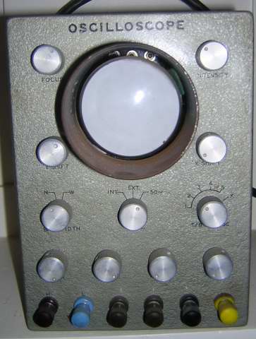
Murray has got a quite typical old CRO he's doing up, and sent photos.
This is a fairly basic uncalibrated audio CRO, but it can be improved in several ways, for example changing the Y and X inputs from screw terminals to BNC connectors, adding a graticule (scale) to the screen, and a calibrator providing a standard squarewave.
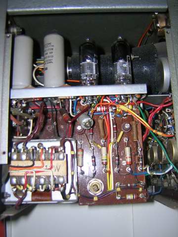
The left side comprises the Y-amplifier at the front, and the HT power supply at the rear. Trimmer caps such as the “beehive” type (at centre), and the Y-calibration pot (lower centre) should never be adjusted unless you really know what you are doing.
Just like a guitar amp of similar vintage, the power supply can electrolytics and the resistors, particularly 1 Megohm and above, should be carefully checked and replaced if at all suspect or off value by more than their marked tolerance (or +/-10%).
Similarly, the front panel controls, switches and pots, get dirty and scratchy and generally need a good clean. The multi-pole switches in particular normally require careful cleaning as they are normally specials and practically irreplaceable, but broken switch wafer can be glued back together if done carefully.
The small CRT can be seen above inside its mu-metal magnetic shield. Note that this shield should be treated like fragile glass and should not be knocked, hammered, drilled, sawn, etc, or it will lose its magnetic shielding properties.
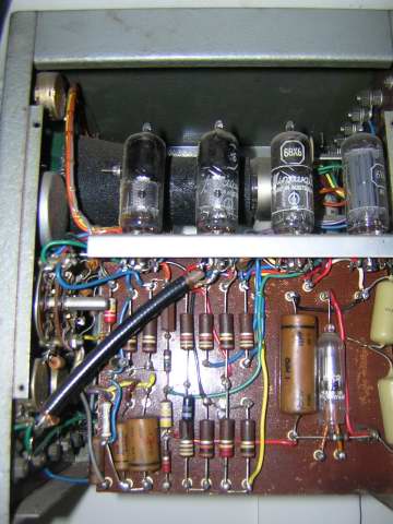
The right side contains the timebase, X-amplifier, and EHT supply at the rear. The glass tube lower right is the “peanut” EHT rectifier diode.
At the very rear we can see that a cap has already been replaced by a series pair of modern caps, and given the position these will almost certainly be in the EHT supply.
Know you enemy - wherever you encounter waxed paper caps (brown waxy cylinder alongside the EHT rectifier and a couple at lower left) they should be replaced on sight. If they are not already horribly leaky, they soon will be, and these days they simply aren't worth messing about with - replace. (Note the black end rings which indicate which lead is connected to the outer cap foil. In critical situations this end should be the one connected to ground, or to the driving circuit).
You can normally pick a Miller by the X timing caps being more-or-less in pairs, but in this case it looks like a single progression and more like the Heath mentioned above.
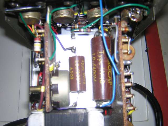
The bottom view shows the Y-board left, and the X board (right), and something of the interior of the busy control front panel.
The brown caps (centre) are aren't much better than waxed paper and must also be seriously suspect. These ones look intact but it is very common for this style to develop cracks around one end, and if so these must be replaced since they have been open to moisture ingress.
If you have a vintage item of test equipment, or perhaps a repair or restoration you would like to share (or are having problems with), please feel free to contact me.