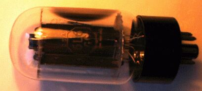
The 6L6 started out as a fairly low-power general-purpose pentode in a metal version with an anode Pdis around 12.5 watts. Over time this was upgraded through -G, -GC, and -GT versions to 30 watts for todays versions. Popular and rugged, used in many amps, most notably Fender's.

Heater Voltage ................................ 6.3 V
Heater Current ................................ 0.9 A

Direct Interelectrode Capacitances (approx)

Pentode
Input ......................................... 10 pf
Output ........................................ 6.5 pf
Grid to Plate ................................. 0.6 pf

Maximum Ratings (Design Center Values)

Pentode
Plate Voltage ................................. 500 Volts
Grid No. 2 Voltage ............................ 450 Volts
Plate Dissipation ............................. 30 Watts
Grid No. 2 Dissipation ........................ 5 Watts
Push-pull (fixed bias)
Push Pull Class AB1 Amplifier
Plate Voltage ................................. 330 V
Grid No. 2 Voltage ............................ 330 V
Grid No. 1 Voltage ............................ -24 V
Peak Grid No. 1 Voltage........................ 48 V
Plate Current (Zero Signal) ................... 122 mA
Plate Current (Maximum Signal) ................ 184 mA
Grid No. 2 Current (Zero Signal) .............. 5 mA
Grid No. 2 Current (Maximum Signal) ........... 11 mA
Load Resistance ............................... 3.8KΩ
Power Output (approx) ......................... 31.5 W

Push Pull Class AB1 Amplifier
Plate Voltage ................................. 400 V
Grid No. 2 Voltage ............................ 300 V
Grid No. 1 Voltage ............................ -25 V
Peak Grid No. 1 Voltage........................ 50 V
Plate Current (Zero Signal) ................... 102 mA
Plate Current (Maximum Signal) ................ 152 mA
Grid No. 2 Current (Zero Signal) .............. 6 mA
Grid No. 2 Current (Maximum Signal) ........... 17 mA
Load Resistance ............................... 6.6KΩ
Power Output (approx) ......................... 34 W

Push Pull Class AB1 Amplifier
Plate Voltage ................................. 450 V
Grid No. 2 Voltage ............................ 350 V
Grid No. 1 Voltage ............................ -30 V
Peak Grid No. 1 Voltage........................ 60 V
Plate Current (Zero Signal) ................... 95 mA
Plate Current (Maximum Signal) ................ 194 mA
Grid No. 2 Current (Zero Signal) .............. 3.4 mA
Grid No. 2 Current (Maximum Signal) ........... 19.2 mA
Load Resistance ............................... 6.0KΩ
Power Output (approx) ......................... 50 W

Push Pull Class AB1 Amplifier (Ultlin)
Plate Voltage ................................. 410 V
Grid No. 2 Voltage ............................ 410 V
Grid No. 1 Voltage Derived from
Cathode Bias Resistor ....................... 220Ω
Peak Grid No. 1 Voltage........................ 68 V
Plate Current (Zero Signal) ................... 134 mA
Plate Current (Maximum Signal) ................ 155 mA
Load Resistance ............................... 8.0KΩ
Power Output (approx) ......................... 24 W

Push Pull Class AB1 Amplifier
Plate Voltage ................................. 360 V
Grid No. 2 Voltage ............................ 270 V
Grid No. 1 Voltage ............................ -22.5 V
Peak Grid No. 1 Voltage........................ 45 V
Plate Current (Zero Signal) ................... 88 mA
Plate Current (Maximum Signal) ................ 140 mA
Grid No. 2 Current (Zero Signal) .............. 5 mA
Grid No. 2 Current (Maximum Signal) ........... 11 mA
Load Resistance ............................... 3.8KΩ
Power Output (approx) ......................... 18 W
Total Harmonic Distortion ..................... 2 %

Push Pull Class AB1 Amplifier
Plate Voltage ................................. 360 V
Grid No. 2 Voltage ............................ 270 V
Grid No. 1 Voltage ............................ -22.5 V
Peak Grid No. 1 Voltage........................ 45 V
Plate Current (Zero Signal) ................... 88 mA
Plate Current (Maximum Signal) ................ 132 mA
Grid No. 2 Current (Zero Signal) .............. 5 mA
Grid No. 2 Current (Maximum Signal) ........... 15 mA
Load Resistance ............................... 6.6KΩ
Power Output (approx) ......................... 26.5 W
Total Harmonic Distortion ..................... 2 %

Push Pull Class AB1 Amplifier
Plate Voltage ................................. 450 V
Grid No. 2 Voltage ............................ 400 V
Grid No. 1 Voltage ............................ -37 V
Peak Grid No. 1 Voltage........................ 70 V
Plate Current (Zero Signal) ................... 116 mA
Plate Current (Maximum Signal) ................ 210 mA
Grid No. 2 Current (Zero Signal) .............. 5.6 mA
Grid No. 2 Current (Maximum Signal) ........... 22 mA
Load Resistance ............................... 5.6kΩ
Power Output (approx) ......................... 55 W
Total Harmonic Distortion ..................... 1.8 %
![]()
Circuit of a simple amp using a Fender two-knob tonestack and a pair of 6L6's. This uses an unconventional bias supply using a divider across the main HT supply. This works but is wasteful and not very satisfactory at higher powers like this.