The Lamington II - a higher powered DIY low cost 50W guitar amp
built with readily available “over the counter” parts!
by Grant Wills
If you have specific questions about this build you can e-mail Grant at:
![]()
|
http://www.ozvalveamps.org/ava100/ava106lamington2.html | Created: 02/12/09 | Last update:
02:50 19/04/10
<<< OzValveAmps |
The Lamington II - a higher powered DIY low cost 50W guitar amp
built with readily available “over the counter” parts!
by Grant Wills
If you have specific questions about this build you can e-mail Grant at:
![]()
| Update; Introduction, At a glance, Caution, Design, Power supply, Output stage, Phase splitter, Preamplifier, Construction, Components (general, valves, power supply, other), Conclusion. |
I've recently had the opportunity to prototype a couple of variants to the Lamington II amp. This was in part due to the fact that supplies of the original power and output transformers have dried up, and to ensure that the design is still able to be built by the next generation of constructors, I have experimented with suitable alternatives to the original transformers.
The initial idea was to revert to a quadrupler supply using a pair of M6672 rather than the hextupler, however this significantly reduced the output power using 6L6's. I really wanted to approach the 50W output power of the original Lamington II, but even with a lower load impedance on the output valves the max output power dropped to approx 20W.
This indicated that the design needed to revert to the original hextupler power supply to provide HT of approx 450V DC. Choices of alternative power transformers is fairly limited, but I settled on 2 M6674 transformers (30V 2A) using the 27.5V taps with the secondaries in series as per the first Lamington amp. A variant of these transformers have been recently cleared out at Jaycar @ $16 ea and stocks of the M6674 are readily available at Jaycar and Altronics @ $27.95 ea.
With the two 27.5V secondaries in series into the hextupler, HT of 450V under load was obtained successfully. The next challenge involved providing a substitute for the original Atlas T18 output transformer. The only readily available (read: off the shelf) substitute is the Altronics M1130 transformer which is rated at 40W compared with the T18's 60W rating. However as the goal was to approach and not necessarily meet the full 55W power of the original amp, a M1130 was wired into the test amp. The good news is that while the full 55W of the original amp was not achieved, the amp produced 47W at clip - a very satisfying result.
So all this to say that the Lamington II lives again! I attach an amended schematic for the amp and power supply for those who wish to try their hand at this amp. Obviously if a constructor can get their hands on the original transformers - great - however, it is good to know that not only are alternatives available, they have been tested with very favourable results!
G.W.Updated version 1.1 27/3/10 - current
Power supply circuit (150kb), Pre and main amp circuit (217kb)
New: 2/12/09
update: 4/12/09
Encouraged by the success of constructors building the first “Lamington” amp, and receiving feedback that the amps built sounded really great, I decided to see if the basic design could be uprated to a 50W version.
I decided initially to build a simple single channel version of the Fender AB763 circuit using the proven ideas of voltage multipliers and speaker line transformers.
This amplifier is designed for the person who has a little more experience in building amplifiers - it is a higher powered design with higher voltages.
Again, it was designed and constructed to prove that you can build your own amp using readily available “off the shelf” components here in Australia at low cost. Depending on how adept you are at scrounging certain components to save costs, the maximum cost to build this amp will be less than $250. It was designed to be built without access to a workshop, and in fact the prototype was constructed in my city apartment to prove that it could be built without special facilities or tools.
Version 1.0 - for reference only
Power supply circuit (135kb), Pre and main amp circuit (212kb)Updated version 1.1 27/3/10 - current (see above)
Power supply circuit (150kb), Pre and main amp circuit (217kb)
- Common low voltage transformers
- Multiplier HT power supply
- 12 volt heaters
- Bias supply
- 1 megohm input resistance
- 12AX7 preamp
- Fender tonestack
- Balanced 12AX7 LTP phase-splitter
- 2x 6L6's
- Inexpensive 100V-Line output transformer
- 50 watts output

|
CAUTION!!!
It needs to be said that this amp generates potentially lethal voltages. It cannot be overstated that you need to exercise extreme caution when measuring voltages etc., on a working amp. NEVER hold the chassis with one hand while you are probing with the other hand. Put one hand in your pocket and probe with the other with the negative multimeter probe firmly clipped to the chassis earth point. Don't forget that even when the power is turned off, potentially lethal voltages may still exist in charged capacitors in the amp. Before working on or modifying the amp, wait for 5-10 mins to allow all capacitors to discharge. (Or better, use a clip-on lamp load to discharge the supply). The front panel neon tells you if there are still voltages present. Working on valve amps need not be dangerous if you apply due care, common sense and maintain a healthy respect for over +450V of high voltage. |
The design for this amp is conventional with the exception of the power supply, which uses some unorthodox techniques to develop the +450 volt high tension supply. The design objective was to provide a 50W output using 6L6GC output valves.
The power supply again uses voltage multiplier techniques to produce the +450 HT. The main power transformer is a clearance DSE M0144 - I have seen them cleared at Jaycar for $19.95 and also Tortech in Strathfield here in Sydney are clearing them for $15 - seems that they are available cheaply at just the right time for this amp.
The 56V from this transformer is applied to a voltage hextupler (six times multiplication) - alternatively called a charge pump which multiplies the voltage to +450 volts. Just in case you think that we are getting something for nothing, the current that can be drawn from the 450V supply is only a sixth of the current available from the transformer's 56V input. As the transformer is capable of 2A of current, it can easily supply the 250ma of current required from the +450V supply. The valves also need 6.3V for their heaters which is provided by a second low cost transformer.
Tests on the power supply were very encouraging and well within the ballpark needed for this design. Output voltage with no load was a little over 500V DC, loaded to 150ma was 458V (68.7W) and loaded to 350ma was 421V (147.4W). With the approx 250ma load of the 2 X 6L6's HT is about 450V (112.5W) which is about optimum. This regulation tracks pretty much the same as the valve rectifier version of this amp (500v standby - no load, 450v loaded) - this simulates the “valve rectifier sag” of other vintage amps.
As the amp needs a source of fixed bias, this is generated as shown in the power supply schematic. It follows the bias arrangements of numbers of old Aussie valve amps which used a voltage doubler supply and tapped AC from the “hot” end of the HT winding. I've used this successfully in the past and it works well and obviates the need for another transformer.
Referring to the circuit diagram of the amplifier, and looking at the bottom right of the diagram you can see the output stage. There are two 6L6GC power valves in the output stage in push- pull configuration producing 50W of output power. Each anode connects to each end of the output transformer primary winding with the +450V high voltage applied to the centre tap of the transformer. The secondary winding of the transformer drives the speaker.
In the prototype, I used an ATLAS T-18 60W transformer which is ideal for this application.
To the left of the two power output valves is a dual triode valve in a configuration known as a phase splitter. The purpose of this phase splitter is to provide out of phase signals to drive the two output valves. The phase splitter is configured so that the signals at its anode and cathode are out of phase with each other. These signals are applied to the grids of the two output valves to provide the “push-pull” drive required.
Located at the top of the circuit diagram is the preamplifier, or “front-end” of the amplifier. The input signal from a guitar is applied to the grid of the first valve. At the anode of this first valve there will be an amplified version (gain) of the input signal. This is applied to the frequency selective tone controls which provide bass and treble boost and cut. The output of the tone control is applied to the grid of the second preamp valve which drives the volume control.
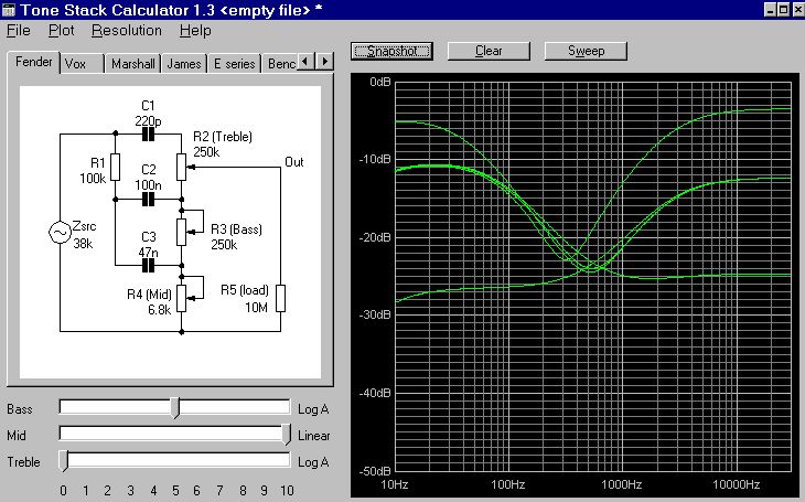
Tonestack response from Duncan's Tone Stack Claculator
A goal of this amp design was to keep the costs of construction to a minimum. In prototyping this amp, I was also mindful that most people constructing it will have limited metal working experience and facilities. In addition, commercial rack cases and cabinets can be rather costly. A solution to these constructional challenges came in the form of a readily available, low cost ($5.99) lamington cake tin from Big W or K-Mart. An inverted cake tin provides an attractive, teflon coated chassis which is ideal for the amp.
There are a number of holes to be drilled in the chassis. I recommend that you mark out grid lines for the holes with a soft pencil. It really helps you see where you are going. There are holes for the transformers, holes to pass the wires from the transformers under chassis, holes for the valve sockets, holes for the front panel controls pots and holes for the mains cable entry, fuse holder and mains switch.
It is highly recommended that you “centre-punch” each hole before you drill it. This will make sure that you drill the hole accurately without the drill bit wandering off target. You can centre-punch the hole with a proper centre-punch or use a large nail as a punch. The drilling of the chassis assumes that you have or can borrow an electric drill with a range of drill bits up to 3/8 inch or 10mm. When you punch the chassis or drill a hole, always place a block of wood on the underside of the chassis. This will ensure that you do not damage the fairly light steel of the chassis.
There is a technique to drill the larger holes (up to 10mm) without the drill bit grabbing the chassis and bending it out of shape. Simply start drilling from a smaller pilot hole and then change drill bits to progressively larger bits to drill progressively larger holes. If you find that your drill grabs the chassis a bit aggressively and bends the chassis, all you need to do is place your block of wood on the underside of the chassis, and gently tap over the top side of the hole with a hammer. This will flatten out the chassis fine.
Two holes drilled in the chassis need to be slightly larger than a 10mm drill bit. They are the holes for the fuse holder and for the mains switch. These need holes of approximately 11-12mm, and they can be made by either filing a 10mm hole out a bit wider if you have a small round file.
Alternatively, if you carefully angle a rotating 10mm drill bit at about 45 degrees to the chassis at several points in a circle with a rotating drill bit through the hole, the hole will be widened sufficiently for the fuse holder and mains switch. This requires care, and the chassis needs to be held fairly securely as the hole is opened up in this way. Initially, try a short burst of power to the drill to give yourself the confidence to do this.
The only holes that are too big to be directly drilled by the drill are the valve socket holes. However there is a solution to this, although it is a bit time consuming. This is accomplished by marking a circle representing the size of the socket hole on the chassis. Then carefully centre-punch and drill about 10-20 2mm holes in a circle just inside the marked circle. Then using a pair of side cutters, snip the chassis between the holes as close as you can to the marked circle. If you have a small file (often available from $2 shops) you can tidy up the final hole.
The insulated jack sockets that I used have small locating key on the front, intended to stop the socket rotating and coming loose. You can simply file these off until the socket fits snugly in the hole, but a better way is to file a small matching notch in the side of your hole that the key can engage in. -rr
The way to guarantee that you end up with a tidy, correctly drilled chassis is to take it slowly, take it easy. You may want to practice your metal skills first on a flattened out tin can to get the feel of it. If the worst comes to the worst and you end up destroying the chassis, buy another one! At $5.98, you have just learned how not to do it!
Both Jaycar and Bunnings stock step-drills, and while a bit pricy, the one I got from Bunnings suits all holes from pots to octal valveholders, and makes a good de-burring tool held in a gloved hand - rr
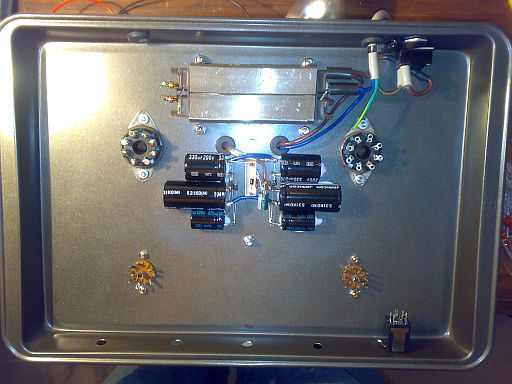
I used my point to point construction method which involves mounting the power supply capacitors to the chassis with silicone sealant with wiring soldered to the caps as anchor points.
Construction of the amp begins by drilling all the holes. Next, mount all the transformers using small nuts and bolts, and then mount the valve sockets and the rest of the hardware. Begin by wiring the mains circuits (mains cable, switch and fuse), and then the power supply, output stage and then pre-amp. As you need to wire the two power transformer primaries in parallel (brown to brown, blue to blue), I suggest you simply solder them together and then tape and heatshrink the joints to be safe. I also recommend that you apply heatshrink to the fuse holder and mains switch for safety.
I chose to construct the amp by using the valve holders as “tag points” and with a few exceptions, every connection could be made in this way. This is done for example in the preamp by wiring 2 X 100K resistors in series with the ends of the series string soldered to the two anodes of the first two valves. If you follow the circuit, there are several components which have a common connection which creates a “tag point”. Where a logical “tag point” is not available, you can simply run a wire from the free component end to the corresponding point in the circuit and anchor the free end with a cable tie to an appropriate anchor point.
Alternatives include using actual tagstrips, or if you're cheap like me, strips of Veroboard bolted or glued to the chassis as tie points, or you could even do a Printed Circuit Board -rr
One very important aspect of construction is to use what is called a “star ground”. This simply means that a point is chosen in the chassis as a common earth point. Every component that connects to earth needs to be connected back to this common "star" point. To create the “star ground” point, scrape the teflon coating on the underside of the chassis back to the bare metal at a central point on the chassis. If you bolt a loop of heavy wire to this bare chassis, this will become the “star” ground. Every “earth” or “ground” connection needs to be returned and soldered to this point. You can "group" earth points around each valve socket and then run a common earth lead to the “star ground”. Wiring the amp in this way will almost guarantee that you won't have hum or stability problems with this amp.
To ensure you have the minimum problems with your amp, I suggest you take your time, and check, check and re-check the wiring of each component against the circuit both before you wire it in and after it is in place. I also recommend that you measure the value of each resistor with a multimeter before you wire it into the circuit to make sure that you haven't mixed up resistor values. (but remember that your fingers have resistance, particularly when measuring high values -rr)
When you have finally finished the wiring, I suggest that you check the high voltage first. You should see over +450V available at the main HT supply. Other key voltage checks are approx -50V at the grids of the output valves and approximately half of the HT volts at the anode of each preamp triode. The phase splitter should have approx +250V at the anodes of each triode.
[Please see Bringing the Amp Up for details on how to liven up your build safely in stages.]
General Components
And now, some comments on parts availability. All of the parts with the exception of the valves and the four high voltage capacitors in the power supply are readily available from Jaycar and Altronics. Be open to the possibility of scrounging resistors, capacitors from old TV sets, VCR's etc. If you can get your hands on such an old piece of gear, you will probably find most of the smaller electronics parts for your amp. Where possible, check any salvaged component for correct value before using it in your amp.
Valves
While 12AX7 valves are available from Jaycar, they are a bit pricey. My recommendation is to purchase your valves from Ebay. You can regularly see 6L6GC valves for approx $60 a pair and 12AX7's and 12AT7's for $10 from Australian sellers.
Power Supply Capacitors
The 470uf 100V, 330uf 200V and 220uf 250V capacitors are available from Futurelec Electronics in Melbourne. Another option (free!!) is available however. Do the rounds of your local computer repair shops, and ask for any faulty/dead computer power supplies that they may have lying around. These supplies each contain a couple of these 200V capacitors (not to mention a host of other useful components, fan, semicons, opto, resistors, caps, case). Old computer monitors contain 220uf 400V capacitors.
These salvaged capacitors are what I used for the prototype and work really well. The values I used were as per the schematic, but you have some flexibilty with values as they are non critical. Another source of capacitors is to ask your local film processing shop to give you any disposed flash cameras. These contain a 80uf or 120uf 330V capacitor which are useful alternatives (plus a LED or neon, and AA battery).
Other Components
There are several sources available for each component, so you should have no problems locating the parts that you need. Parts are available from Jaycar and Altronics stores directly if you are near them, or alternatively, these suppliers provide excellent mail-order service by phone or the Web.
The prototype fired up with very pleasing results - It sounds brilliant - very clean, warm, big sound typical of vintage Fender amps of 35-40W class. I haven't yet had a chance to try it out through a bigger cab, but I'm sure that the sound will be even bigger again.
I hope you have a great time constructing and enjoying the sound of your amp!

Note the tightly twisted heater wiring (blue)
Disclaimer:
Australian Valve Amps has no connection with any supplier. Intending constructors are advised to shop around and compare prices, particularly on major components such as transformers and valves.
|
|