For noise and lightning.
Contains:
In the days when a home entertainment center was called a radiogram, and fridges didn't have supressors, coil manufacturer Aegis sold a plug-in cylindrical Bakelite mains filter.
Todays “Surge Busters” don't even begin to compare to a proper line filter using inductors and capacitors, as well as the MOV's used alone in cheap protectors.
MOV's, or Metal Oxide Varistors also known as VDR's - Voltage Dependant Resistors, act somewhat like Zener diodes in that they conduct when their voltage rating is exceeded, thus clamping the peak voltage across them.
In fact pure voltage clamping, which is all these do, is of very limited value on its own. The real issues are the spike risetime, how fast it changes voltage, and available slew range. MOVs limit the voltage to within the peak mains voltage but they can do nothing about spikes that are within that range or reducing their slew rate and ability to radiate into the equipment.
Home recordists notice the difference using a proper line filter when odd “noises-off” such as the fridge switching or drill whine no longer features on tracks. MOV clippers alone won't help because these signals are inside their clipping range.
Normal operation of motors and such on the mains is not the cause of widespread electronic mayhem and computer failure as Buster sellers would like you to think. Nor do these devices give the protection implied.
The real killer is lightning and lightning induced spikes on the power system. And the normal amplifier victim is the solid-state rectifier particularly the bi-phase type such as used in Fender Twins.
Early application of silicon diode rectifiers normally had a small cap across each diode to protect it from voltage spikes. Later power diodes were avalanche protected, meaning that they could suffer a reverse breakdown for a limited time without damage. Many later Australian valve amps used bridge rectifiers and these tend to be inherently self-protecting against reverse overvoltage.
The ability of any protection to protect the diodes require that the balance of the spike voltage be dropped somewhere else than across the diode. Normally this would be the effective impedance of the supply transformer, but with a MOV connected directly across the mains, as in a surge buster, where will the balance of the voltage drop?
The answer is stray inductance in the mains wiring. Well rather than critically depending on and unknown variable it is better to introduce some known inductance of your own, then the MOV's at least have a fighting chance.
So New Years 2002 I was mixing a show in the middle of a raging electrical storm, keeping my fingers crossed, and promising myself I'd finally build a big line filter. The show outside totally upstaged the show inside but we got through without mishap.
The bottom line is that because of the awesome power levels there is nothing that will protect against a direct strike to the line right outside, all you can do is improve your chances. And because of the radio frequency nature of lightning a low-pass mains filter with inductive elements in series can provide much more protection than any number of MOV's alone.
A mains filter has to protect against two forms of spike, differential between active and neutral and over-volting the equipment; and common-mode where both active and neutral spike together with respect to ground which may flash trannies and other fittings to ground.
The sparking urn thermostat in the kitchen will be producing differential noise, while lightning tends to lift the whole power system above ground so is generally common-mode.
It is important that any device using a MOV/VDR be fused since they age low in voltage and typically fail short circuit. Early unfused surge busters started house fires.
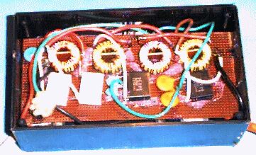
This is the “festival” version made up for use with a small machine at a small weekend riverside gathering of a couple of hundred where fairly informal music making would feature.
It was constructed to provide stage-end facilities for a backline, small PA and a few Par cans.
It has a 15 amp circuit-breaker for a little under 4kVA, sufficient for a 6.5kVA machine. It's mounted where it is because that's about the only place it would fit in the box
Following the c/b are two neon pilot lights, a green one between active and ground and a red one between neutral and ground. These serve as a warning of reversed active-neutral, and if both light warn of an open ground, tings off the mikes and stands, and a nervous gig.
A fat differential-mode MOV and cap are followed by a 3-section balanced LC filter with more MOV's and caps in common mode.
A metering loop is brought out to allow simple metering using a tong-tester.
Ground is brought to a heavy bolt available on the exterior to connect a ground spike. Internally there is provision for an earth-neutral link when being used with a machine (floating terminals bottom left; this link should not be fitted for normal mains operation as it should already be linked at the switchboard, and may defeat any ELB/RCD's fitted).
The caps are X2-series mains rated for supression duty, bought new from WES. Don't use anything less.
The powdered-iron torroidal inductor cores and wire were recovered from dead old computer power supplies.
Normally re-using copper winding wire is not recommended, but in this case a little insulation damage is insignificant.
The coils on each half core must be counter-wound so that the magnetic field due to the go and return currents tends to cancel, avoiding core saturation (apply Fleming's Right Hand Grip rule). The active and neutral windings are held apart by blank printed board offcuts cut to fit and glued in place.
The coils consist of around 10 turns each, the exact number is unimportant as long as there are an equal number of turns on each half of each core so the go and return currents generate equal and opposite magnetic fields in the core. Naturally the wire must be heavy enough to carry the intended current.
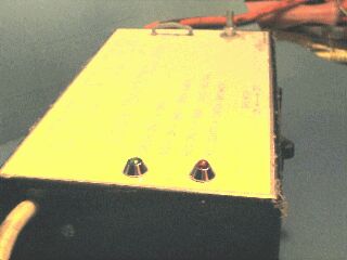
Neons at the front, metering loop and earth bolt at rear, circuit breaker on right side.
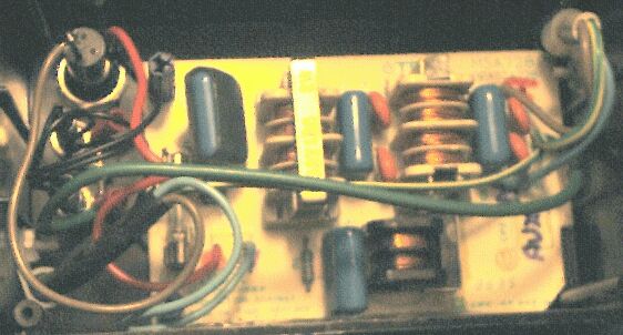
This little brother is more conventional because it is basically a repackage of a commercial filter recovered from a defunct heavy-duty computer power supply.
This has a 4 amp 3AG fuse on the front and a 5 amp fuse internally in case someone gets a 35 amp one from their car.
It also has neon tell-tails and again their metal bodies are specifically connected to mains earth. The fuse visable is in fact a spare in a blank holder, the real fuse above it hidden under the big cap.
Apart from having an unused side-arm filter for the monitor power output (bottom), the circuit is generally similar to the 15 amp filter above.