Maths
If maths is a language, then this is a tourist phrasebook.
Don't panic.
A quick guide to what you really need to know, ...and how to fake the rest.
Contains:
|
Instant technician, Calculation methods - Estimation, Paper and pen, Slide rules, Calculators, Computers, Constants - Greek alphabet, Names of powers of ten, Radian measure, Trig functions, Sinewave, Pythagoras' Theorem, Decibels, Logarithms, Exponentials, Filters - Response estimation, Vectors, Complex Numbers, Polar notation, A smattering of Calculus - Statistics, Vital formulae - Resistance - Ohm's Law, Power, Reactance, Impedance, Other stuff - Mains colour codes, The resistor colour code, Prefered value series
|
Instant technician
I have always struggled with maths and have never found it easy. There are a few lucky individuals who can glance at something really horrible and say “oh yes, but that factorises with Sin x2”, or whatever.
It does?
Not me. I can only admire from the foothills.
Then there are those who throw in a lot of sigma, phi, and pi in the sky to bamboozle and obsficate rather than communicate and enlighten. A pox on them I say - it's hard enough already.
So if, like me, your maths isn't too crash hot, this is about how I have been keeping my head above water and fakin' it all these years, and how you can too. ;)
It's a practical reality that if you are going to work on amplifiers sooner or later you will want to calculate something such as anode dissipation or output power from your current and voltage measurements.
Calculation methods
There are a range of ways of crunching numbers and each has its role.
Estimation
Possibly the most important skill in engineering in general is the ability to estimate. This may range from an educated guess to a back-of-the-envelope or ball park calculation. Naturally the value of an educated guess depends a lot on the experience of the guesser, but can be surprisingly close if well informed.
Real quick, how many watts is 12.6 volts at 7.9 amps?
'Bout 100.
Round 12.6 down to 10, and 7.9 (8) up to 10, 10 squared is 100.
Checking, the exact answer is 99.54 so this estimation is better than 0.5% error. Together with squares (below), using this up/down rounding technique I can have an answer while others are still chanting their times tables, and get through a series of calculations before I forget what I was looking for in the first place.
Electronics for the most part isn't all that precise, ten, perhaps five percent at best, so you really only want to know what the first two or three digits are and where the decimal point is. And you don't actually want a number anyway, you want a result and the number is only a stepping stone to getting that result.
If you keep your rounding up and down balanced and honest this sort of rough calculation can be close enough.
Keep an eye on orders of magnitude, powers of ten, where the decimal point is. When somebody tells you they measured 920mA through a 12k resistor in their amp, alarm bells should ring.
Paper and pen
There should always be pad and pen on the bench for noting measurements, lead colours, side observations to follow up later, traced circuit fragments, and a bit of instant number-crunching. This makes it easy to go back and see where you misread a 1 for a 7 on your DVM, or whatever. A bit of a job trail because it's surprising what you forget, and it brings focus to your investigations.
Slide rules
Don't laugh. Most slide rules can be used like a full-on scientific calculator, log tables, and require no batteries. Unlike many calculators, every one of my slide rule collection still works perfectly.
Slide rules come in many specialised forms, right down to simple cardboard slides. I have one from a resistor manufacturer that does Ohm's Law and the Power calculations with one slide setting, and I have used it on the bench daily since the 60's.
Calculators
Like most people I have a few calculators scattered around and the ones that still work still get used from time to time.
Particularly useful keys include square root and reciprocal (1/x). For heavier work a full set of Trigonometric or Trig functions is needed including polar-to-rectangular and inverse. Engineering notation is handier than pure scientific notation. Avoid calculators that are geared to statistics functions as these tend to displace useful electrical engineering functions. Solar recharge is handy.
Computers
There are a huge number of programmes that will do electronic calculations ranging from the very simple to circuit simulators like Spice, TINA, and Electronic WorkBench. Programmes like these are a full-on hobby all on their own.
The big danger with simulation is that you can mistake it for the real world where the gear has to finally work. Despite their attempts simulators such as EWB can't displace the prototype stage where the rubber hits the road, voltage hits the anodes, and reality asserts itself.
Sure you can computer model anything given enough detail, but at some point it gets better to model your circuit with real components. Designers often call this first-build the “birdsnest” stage because of the way additional components get festooned around the circuit as you progress from the idea to the working reality.
Under Windoze there is a calculator that can be fed and read using copy/paste.
I have found QBasic very handy in the role of a programmable calculator, in particular its screen plotting functions to visualise data, for example while designing horn loudspeaker cabinets.
It's also useful where you want to do something many times over and record the result, such as plotting bandwidth.
Each little programme you create, if done in an orderly fashion, provides pre-assembled and tested building blocks for the next project. Creating new personalised tools gets easier as you go along.
[Disclaimer: I am not a language imperialist for any of the languages I have written in, just pragmatic. If AdonisLite, Dweezle-II, or Numberblatt works for you, then use it.]
Constants
What I carry around in my head.
Pi = 3
2 Pi = 6
The implicit multiplication convention is that “2 Pi” means “two times Pi”. Mathematicians sometimes use “.” for the same meaning.
Programmers Pi:
Pi# = 4 * ATN(1):' double precision
(Pi# = 3.141592653589793 note: radian angle)
Root 2 = 1.4 (a bit less than half as much again)
Squares from 1 to 10, and 12 (I have no idea why I don't use 112)
1, 4, 9, 16, 25, 36, 49, 64, 81, 100; 144
Apart from helping to estimate sums and products (multiplication) these also allow you to estimate square roots. Calculating a square root without assistance is a pretty nasty business, so why would you bother? How about finding the output power of your amp given the load impedance and the voltage you measure across it? (see Power below)
Scientific and engineering notation, powers of ten.
12345.6 = 1.23456 x 10⁴ in scientific notation
and 12.3456 x 10³ in engineering notation.
106 x 103 = 109
106 x 10-3 = 103
10-6 x 103 = 10-3
10-6 x 10-3 = 10-9
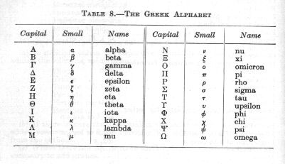
The Greek alphabet
Greek letters both upper and lower case are liberally sprinkled through electronics formulas. It is helpful to know their names and common usage to decode what the author is on about.
Some examples of common usage (small unless noted):
- alpha, beta - transistor gain
- delta - small change
- theta - an angle or rate of angular rotation
- lambda - wavelength
- mu - micro, 10-6
- pi - ratio of circumference to diameter of a circle, 3.14159265359...
- sigma (capital) - the sum of all the parts
- tau - time constant
- phi - phase angle
- omega (capital) - resistance in ohms
- omega - angular rotation, 2 Pi f
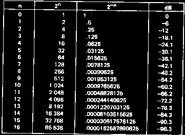
Names of powers of ten
| pico, p | 10-12 |
| nano, n | 10-9 |
| micro, µ (mu) | 10-6 |
| milli, m | 10-3 |
| units | 1 |
| kilo, K | 103 |
| mega, M | 106 |
| giga, G | 109
|
Radian measure
Radian measure is only another way of expressing an angle.
360° = 2 Pi radian (“c”)
360° = 6.28c
w (little omega) = rotational velocity in radian/sec
w = 2 Pi f
where f is frequency in Hertz or cycles per second.
Trig functions
Trigonometry relates the length of the sides of a right-angle triangle to its other angles and is very useful in AC theory and analysis.
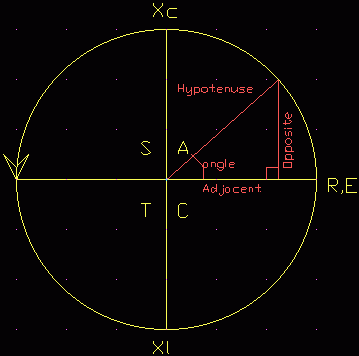
Three magic words to help you remember the trig relations:
SOH, CAH, TOA
Meaning:
Sine (theta) = Opposite / Hypotenuse
Cosine (theta) = Adjacent / Hypotenuse
Tangent (theta) = Opposite / Adjacent
Where theta is the angle.
The hypotenuse is the longest side of the right-angle triangle.
The letters CAST are a mnemonic to remind which functions are positive in which quadrants. Reading anti-clockwise from C:
- C = Cosine is positive in this 4th quadrant
- A = All are positive in this 1st quadrant
- S = Sine is positive in this 2nd quadrant
- T = Tangent is positive in this 3rd quadrant
In AC analysis the circle is a unit circle and the frame of reference or axies are rotating anti-clockwise at the rotational frequency in question. The right hand X-axis, R, E, is taken as the reference, generally resistance or applied voltage. Then this is called a phasor diagramme.
Sinewave
Also useful is the expression for the instantaneous voltage of a wave:
e = Em Sin(theta)
where:
Em is the maximum or peak voltage of the wave
theta is the phase angle along the wave
Pythagoras' Theorem
a2 = b2 + c2
hypotenuse2 = adjacent2 + opposite2
hypotenuse = Sqrt(adjacent2 + opposite2)
Decibels, dB
The original unit of signal power on the telephone network was the Bel. This was found too large for practical use so deci-bels, one tenth of a Bel, became the common usage. No other metric prefixes are used with the Bel.
The decibel scale is not an absolute line like a ruler, but is relative. It is a shorthand way of expressing large ratios, and thus dB's have no meaning on their own until they are referenced to something.
There are many different dB scales in use for different needs, including:
dBm - signal power ref to 1mW in 600 ohms
dBV - signal voltage ref to 1V
dBu - signal voltage ref to 1uV
dBSPL - sound pressure level ref to 0.0007 dynes/cm2 at 400Hz. This is almost 10-16 watts and about the threshold sensitivity for young ears at 1kHz. This is also the reference level for loudspeakers when measured one metre directly in front, and driven by 1 watt.
dBA - this is actually a bandwidth limiting (A weighting) to simulate hearing limitations for a subjective reading. Weighting should be treated with caution as it takes no account of the nature of the noise and how annoying low-level sounds can be.
| dBSPL | Example |
| 140 | Pneumatic riveter, hearing damage in short-term |
| 130 | Boiler shop, hearing damage in medium-term |
| 120 | Thunder, pain threshold, hearing damage in long-term |
| 110 | Motor horn at 1m |
| 100 | Loud orchestra; inside airliner |
| 90 | Inside motor bus |
| 80 | Voice shouting |
| 70 | Noisy office |
| 60 | Conversational speech at 1m |
| 50 | Average office |
| 40 | Quiet speech at 1m |
| 30 | Very quiet dwelling |
| 20 | Whisper at 1.5m |
| 10 | Watch ticking at 0.6m |
| 0 | Threshold of hearing for young ears
|
The Richter scale for earthquakes is also a dB scale.
But these all come in only two basic types, voltage/current, or power.
Calculations of decibels from voltage, current, or power levels require the use of logarithms (see below).
Voltage or current
dB = 20 Log10 (Vin/Vout)
6dB = twice
-6dB = half
20dB = ten times
40dB = a hundred times
60dB = a thousand times
Power
dB = 10 Log10 (Pin/Pout)
3dB = twice
-3dB = half
10dB = ten times
30dB = a thousand times
60dB = a million times
Logarithms
There are confusingly two kinds of logarithms, one to the base e, and the other to the base 10.
The first sort are called Natural or Napierian logarithms. e is a constant like Pi and is called the exponential number and equals 2.7183... (see below, note: be sure to say “expo-nen-shal”, not “expo-tent-shal” or you will blow your cover)
Their symbol is Ln.
The second sort, base 10, are called common logarithms, but often just logarithms. These are the ones we want for dB's.
Their symbol is Log.
Microsoft's QBasic helpfully has a function called Log(x). Unhelpfully this actually returns the Natural log Ln(x). And this is the only log function it has. This requires a change of base:
Log10(Av) = Lne(Av) / Lne(10)
' LogBit Ln to Log in QBasic e.g. dB = 20 log Av  Roly Roper 9/7/98
INPUT “Voltage gain =”; Av: ' voltage gain
dB = 20 * (LOG(Av) / LOG(10))
PRINT dB
END
Exponentials
In another one of those areas where maths is “unreasonably effective”, a vast range of natural processes follow an exponential law of growth and decay.
From capacitors to plant growth, from your coffee cooling to the spacing of your guitar frets.
This law is of the general form:
yt = y0 e±kt
where:
y0 is the initial value at t = 0
yt is the value at time t
t is time, generally in seconds (or “x” if it's not a time-factored process)
k is the curve constant that sets how rapidly it rises or falls.
(+ve if growth, -ve if decay)
e (as above) is taken care of in the lookup table.
The value of ekt can be found by tables, calculator or programme.
While having trouble setting the intonation* on a friends Strat copy I finally decided to map where all the parts, nut, frets, bridge, should be.
After putting all the measurements into a spreadsheet (AsEasyAs, a Lotus work-alike) and a bit of graphing it emerged that the fret positions follow the exponential law (they plot a straight line on a log scale).
Dn = A e-kn
where:
Dn is the distance from the nut face to the crown of the 'n'th fret
A is the scale length, the distance from the nut face to the bridge crown
k was found to be -0.05782 for this particular guitar
n is the fret number (the nut, or zero-th fret if fitted, is zero)
The best-fit value for the scale length, A, was 645.5mm, while the measured average was 647.5mm.
These values were obtained using cut-and-try, graphing a perfect fretboard against the measurements, then diddling first A, then k, for best fit. Nothing mathematical. People who use maths a lot call this the empirical method because it sounds better than “blindly groping” or “clueless”.
What emerged was that the nut had been glued at the back of its over-wide slot rather than against the end of the fretboard, so the nut to 1st fret spacing didn't match the rest of the guitar.
After visually best-fitting the two curves I checked and fine tuned the result using RMS-error or Sum of Squares.
This is where you take each fret position error, square it to make all values positive, add them all together, then take the square root for the RMS error. You can forget the root step and simply diddle your A and k values for the lowest value sum of squares, which is minimum error.
(* Intonation is the process of making the notes produced at string/fret positions match the musical scale. We've all experienced the guitar that sounds okay in the root position but goes sour up the neck, well this one was the opposite, up the neck was fine but root chords sounded like porrage.)
Filters
The time constant, tau, of an RC or RL circuit is the time it takes to change two-thirds of the way between the initial and final value.
t (tau) = C R
It is often easier to work with seconds, microfarads and megohms, or milliseconds, microfarads and kilohms.
The charge, Q in Coulomb, on a capacitor relates four quantities, current, time, capacitance and voltage.
Q = I t
The charge is equal to the current in amps by the time in seconds.
Q = C V
It is also equal to the capacitance in farads times the voltage.
Therefore:
I t = C V
A handy scaling is milliamps, milliseconds, microfarads, volts.
This is useful around 555's and in constant current fed timing circuits.
More useful in audio is the corner frequency of an RC network which is given by:
f = 1 / (2 Pi C R), or
w = 1 / C R
A helpful simplification is to deal with R as megohms, 106, and C as microfarads, 10-6, where the answer will still emerge as Hertz (cycles per second).
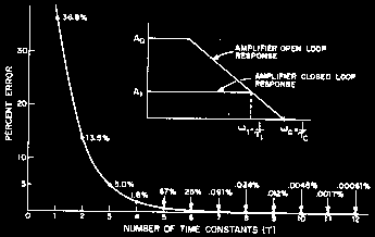
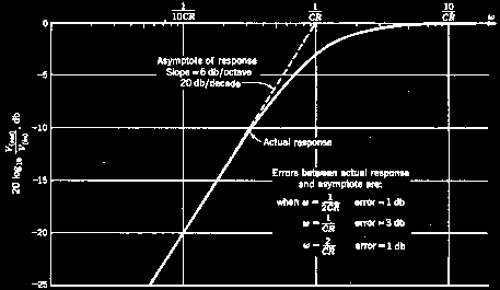
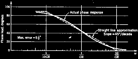
Response estimation
A straight-line frequency response approximation rises or falls at a constant 6dB per octave (half or double the frequency) per CR section. Extra sections add in dB's, so two sections will change from the corner frequency by 12dB per octave. The frequency/phase graph is also called a Bode plot.
The error of a straight line approximation per CR section is only 3dB at the corner, and 1dB at double and half the corner frequency.
6dB/octave = 20dB/decade
Double per octave is ten times per decade.
Half per octave is one-tenth per decade.
20dB is ten times (voltage)
40dB is a hundred times
60dB is a thousand times
The phase angle is 45° at the corner, 0° or 90° at one tenth and ten times the corner frequency, a slope of 45°/decade. The phase error is only 5.5°.
Vectors, Complex Numbers, Polar notation
A vector is a value that has two parts, magnitude and direction. The impedance of a loudspeaker is actually a vector composed of two parts, one resistive, the other an inductive reactance.
Since reactance is at right-angles to resistance the resulting impedance can be expressed in several forms, the most common being...
Complex numbers
A very off-putting name for a simple idea, also known as rectangular form. This is like a treasure map, “go west ten paces then go north five paces”.
Z = (R + jX)
The “j” simply says “turn right (or left), you can't add east to north”.
The 8 ohm impedance of a loudspeaker is composed of about 5.6 ohms of resistance and an equal amount of inductive reactance.
8 = (5.6 + j5.6)
Try applying Pythagoras and check that:
Sqrt (5.62 + 5.62) = ~8
Vectors may also be expressed in polar form as distance/angle or range/bearing. Converting between these two forms is called polar-rectangular conversion.
There is also a lesser used exponential form.
(See also Trig, above)
A smattering of Calculus
A useful idea imported from Calculus is the concept of small change (delta).
We might be doing a valve loadline and want to know what the slope or gradient of a curve is at a given point. Since it is a curve the gradient is constantly changing, but if we take our point and another point a very small distance away, delta, the straight line gradient between the two points will be close enough to the local gradient of the curve itself.
Gradient is 'rise by run' and here is called dy/dx. This pops up as dv/dt, voltage against time, di/dt current against time, and df/de fish box level against Esky level.
Stats
The average of a number of values is given by:
Avg = (V1 + V2 ... + Vn) / n
where:
Avg is the average
V1, 2, 3... etc are the data point values
n is the number of data points
Statistics don't need to be applied much outside manufacturing. If you are building a single amp a bit of tweeking isn't a problem.
But if you're building them by the thousand component tolerances become a worry.
Every component has a tolerance on it's nominal value. If you test a lot of component batches probability theory says that the values should be a normal distribution or Gaussian spread around the nominal value. This is also called the bell curve from its shape.
We expect that most will be near their value and a decreasing number either side. While this is generally true individual component batches tend to be tightly clustered on only a few values, reflecting the precise settings of the manufacturing runs that made them.
Values that lie outside the tolerance band are called outliers, and generally bound for the bin.
In Ye Olde days a pilot run of say 100 radios were built, then closely looked at to find the manufacturing defects, and production rearranged accordingly.
Today we can build 10,000 on our computer doing a maximin or Monty Carlo run and plot the performance difference every combination makes.
Maximin tries every combination of components at the minimum and maximum extremes of their tolerance range.
Monty Carlo does much the same by randomly picking component values, the idea being you can get a less reliable result quicker.
Once the production line starts belting units out you have to deal with failure rate.
We notice that a proportion of units fail in the first few minutes, hours, or days of operation, but that this initially high failure rate falls rapidly to a low level as service life extends from days to months, and remains at this low level until the years start piling on and the failure rate creeps up again.
This is common to most mechanisms, not just electronics, and is the reason behind burn-in to catch these incipient early failures that pass initial tests.
The other side of the statistics coin are probability and random distribution.
“White” noise has a random distribution, that is any level or frequency is equally likely to follow any other. You may hear this called stochastic, meaning “following the laws of probability”. There are several sources of noise in electronic circuits but most of them do not have a random distribution.
Please note that chaos and chaotic systems, while noisy, do not have a random distribution.
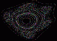
A
Henon fractal, chaotic but not random.
Pseudo-Random noise generators, typically based on a polynomial shift register arrangement such as CRC-16, or similar in software, may be “noisy” enough for audio testing but they are not random. In fact they are totally determined and periodic, it's just that they count in an odd progression. In fact spread-spectrum systems such as Wi-Fi depend on this periodicy to capture the signal.
Vital formulae
If you are happy doing algebraic transpositions then you only have to remember one form each for the resistance and power relationships.
Resistance - Ohm's Law
E = I R
I = E / R
R = E / I
Where:
E = voltage
R = resistance
I = current
Mnemonic: E is always on top
Simplification: work with R in k ohms, I in mA.
Power
P = E I = I2 R = E2 / R
E = P / I2 = Sqrt (P R)
I = P / E = Sqrt (P / R)
R = E2 / P = P / I2
Mnemonic: Power engineers generally talk about “I-squared-R” losses and “volt-amps” rather than watts.
One Horsepower is 746 watts, almost 3/4 of a kilowatt.
One joule is one watt per second.
Reactance
The reactance, X, of a reactive component such as a capacitor or inductor may be thought of as its resistance to AC current, and depends on the frequency.
Capacitive reactance
(current leads voltage by 90°)
XC = 1 / (2 Pi f C)
(ohms, hertz, farads)
CLS
PRINT “XC - reactance of a capacitor - Roly Roper 23/8/99”
PRINT
pi# = 4 * ATN(1)

start:
PRINT “Zero entry to end - 1uF = 1e-6”
INPUT “Capacitance (F)”; cap
INPUT “Frequency (Hz)”; freq
IF cap = 0 OR freq = 0 THEN END
' Xc= 1 / 2 pi f C
Xc = 1 / (2 * pi# * freq * cap)
PRINT Xc; “Ohms”;
PRINT
GOTO start
END
Inductive reactance
(current lags voltage by 90°)
XL = 2 Pi f L
(ohms, hertz, henries)
CLS
PRINT “XL - reactance of an inductor - Roly Roper 11-10-99”
PRINT
pi# = 4 * ATN(1)

start:
PRINT “Zero entry to end - 1uH as 1e-6”
INPUT “Inductance (Henry)”; induct
INPUT “Frequency (Hz)”; freq
IF induct = 0 OR freq = 0 THEN END
' Xl= 2 pi f L
Xl = 2 * pi# * freq * induct
PRINT Xl; “Ohms”;
PRINT
GOTO start
END
where:
XC and XL are in ohms
f is the frequency in Hertz/cycles per second
C is the capacitance in Farads
L is the inductance in Henrys
Impedance
Impedance, Z, may be thought of as the effective AC resistance of a circuit. It consists of two parts, resistive and reactive. Inductive reactance is considered positive (“+j”) and capacitive reactance negative (“-j”). Impedance is expressed in Ohms, but strictly it is a vector with direction as well as magnitude.
For some things such as calculating loudspeaker loads it is sufficient to deal with impedances as simple resistances. Heavier duty work requires Complex numbers (see above).
Other stuff
Mains colour codes
The old and new standard for mains appliance wiring:
Safety earth - green - green with yellow stripe
Active - red - brown
Neutral - black - blue
Note this is for appliance leads such as guitar amps and does not apply to fixed wiring where the old system is still in use. (I guess they don't think there are any colour-blind 'lecco's out there). In a three-phase installation blue may well be a phase active, so watch out!
The resistor colour code
Modern resistors use colour bands in the order 1st digit, 2nd digit, multiplier, tolerance.
Older resistors, particularly of the “dumbel” form, used a body-end-dot marking scheme. The body colour is the 1st digit, the end colour the 2nd, and the dot is the multiplier. These were also often of even-number values such as 250k or 500k (green body, black end, yellow dot) rather than 220k and 470k (e.g. Amplivox).
0 = black
1 = brown
2 = red
3 = orange
4 = yellow
5 = green
6 = blue
7 = violet
8 = grey
9 = white
Prefered value series
10, 12, 15, 18, 22, 27, 33, 39, 47, 56, 68, 82, 100
 <<<OzValveAmps
http://www.ozvalveamps.org/maths.html | Last update:
21:01 24/09/05
|