What's wrong with a normal torch?
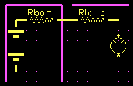
As it happens, the characteristic of batteries and filament lamps are poorly matched.
If you were to take the ratings on a filament lamp literally then you would expect a 3 volt globe rated at 200mA to have a resistance of 3/0.2 or 15 ohms, but when you measure its resistance with your meter it reads less than an ohm.
This is because the resistance of the filament rises by roughly 20 times between cold and full temperature.

Initially the battery is fully charged and has a low self or internal resistance. The lamp is very hot so its resistance is high. The result is reasonable efficiency.
But as the battery runs down its internal resistance rises and its terminal voltage under load falls.
The lamp cools and its resistance drops placing a greater load on the failing battery, and efficiency drops right off.
There is an effective transfer of resistance from the lamp where it gives you useful light, to the battery here it gives only waste heat.
Running a LED directly from a battery with a current limiting resistor has its own problems such as losses in the resistor and failure to light once the battery voltage drops below the LED threshold or cut-in voltage, Vgamma.
Typically this cut-in voltage is more than one cell's worth.
During 2002 the light output of available Light Emitting Diodes (LED's) rose by leaps while the prices fell dramatically.
I had previously constructed a LED torch using a conventional dropping resistor and the brightest LED then available. This was yellow and only about 1Cd.
It was useful, but apart from lacking intensity the monochromatic yellow light produced an unpleasant lack of visual depth of field in the greenery of the bush.
Battery life was better but the poor light output didn't compensate, and the operational end point arrived fairly suddenly while the batteries still had considerable charge left.
At the beginning of 2002 white LED's became available at a few candella and around $7A, with red and yellow at higher intensities and lower prices.
By early 2003 white LED's were up to 10Cd and down to $2A in small quantities. This trend is likely to continue for some time yet.
A number of developments in chip technology were required for the white LED. The key has been the development of ultra-fine chip features allowing 'quantum well technology'.
The LED story has been twofold, trying to get the output up through efficiency, and trying to get the wavelength down towards the blue end of the spectrum by any means possible.
The result now is a LED that emits ultraviolet light.
By itself this might only be a curiosity, but the common fluorescent lamp works by converting internal ultraviolet light into useful visible light using an internal fluorescent coating.
This same trick is now used to produce white LED's, the colour coming from the fluorescent mix used.
Circuit
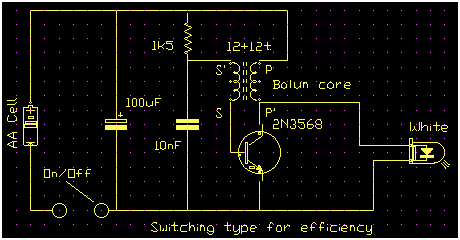
One way to to drive a 3.5 volt LED from a 1.5 volt battery is a small inverter or Switch Mode Power Supply, in this case in the form of a blocking oscillator.
The circuit functions by storing power from the battery in the magnetic field of the transformer on one half cycle, then returning that power to the LED on the other half cycle. Detailed operation is discussed below.

You are not getting something for nothing. The product of voltage and current is power, and this is the same (after losses) on each side.
Operation
1. Start up
Initially the 10nF is discharged and the transistor thus switched off. The 10nF charges via the 1k5 until it gets to about 650mV and the transistor starts to conduct.
2. The Cycle
The coupling back from the collector to the base via the transformer is positive feedback so the transistor is rapidly driven into saturation.
Initially the current is limited by the inductance of the transformer but it quickly rises and as it does the magnetic field in the transformer core builds up, storing energy.
A transformer can only transform a changing current, so when the rise in current in the primary starts to flatten, the feedback starts to falter.
The same process that drove the transistor into saturation now reverses and cuts it off hard, driving the base negative while the field collapses.
The magnetic field in the core now lacks a current to support it and starts to collapse. As it does so it induces a back-EMF in the transformer windings.
The voltage induced in the secondary holds the transistor off.
This is called a back-EMF because it has the opposite polarity to the voltage that initially built it up.
We arrange for the LED to be connected as a catch diode so that the energy stored in the magnetic field is discharged through the LED. When the polarity reverses the voltage across the secondary is effectively added in series with the battery.
The output voltage is automatically set by the LED Vgamma, while the oscillator will continue to run until the battery voltage is very low and effecively dead flat.
The function of the 100uF is to reduce the impedance of the supply and extend available battery life.
The function of the 10nF is to provide a stable reference voltage for the transformer secondary to work against.
Its value is not critical so long as it has a low reactance at the operating frequency and has nothing to do with tuning the frequency. That is determined by the transformer and load.
The circuit will work with just about any transistor with gain, but the most important parameter is its saturation voltage Vsat.
A low Vsat transistor gives much better performance than most common types.
Layout

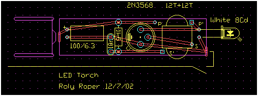
Layout isn't critical and can be freely adapted to any physical form desired.
The PCB layout was done with adapting a 2x AA 'MagLite'-style aluminium torch in mind. I abandoned this idea because the troublesome switch ring would still be used.
Construction
Depending on taste and need you can build it on an etched PCB, strip board, matrix board, mono-pad board (my favorite), or aero-board rats nest style.
The transformer consists of two 12 turn windings on a common balun core.
Take two lengths of thin-ish enamelled copper wire about 2 ft/0.5m long. Wire-wrap wire may also do. It's helpful if you can find two different colours.
Straighten them and lightly twist them together, just enough to keep them together while winding.
Gently bend these in the middle to form a U.
Thread the ends through the holes in the balun core so the core lies at the bottom of the wire U, but don't pull it tight.
Instead insert a couple of matches or a small cable offcut in the U to space it a bit from the core.
Take one of the free wire ends and poke it back through the other hole, and the opposite for the other free end.
Trap another offcut spacer in this end. These spacers make winding easier when the holes fill up later.
Continue like this until you have 12 turns, or you can't get any more on.
Cut off any excess wire, but not too short yet!
One end-pair are the winding Starts (marked S and P), the other the Finishes (marked S' and P').
If you used coloured wire call one colour the Primary and the other the Secondary, otherwise determine with your ohm meter.
The most vital point now is to make sure that the P, S, P', and S' wires go to the correct points so the phasing is correct and the circuit oscillates.
Testing
On initial test and servicing its a good idea to limit the available battery current with a torch globe or resistor until you are sure it is oscillating.
Don't operate without the LED (or other diode) connected. The unlimited spike from the transformer may damage the transistor.
Packaging
As it happened I had a $3A plastic 'karioke' microphone from one of those bargain stores which I gutted, poked the LED down the rubber cable hole from inside, wired the battery via the on/off switch, and a bit of foam padding to stop the battery and circuit from sloshing about.
It has been thrashed for over a year now by kids and adults alike and is still going strong on the original AA cell.
This has turned out to be a very useful format for poking into small places such as the car engine bay, the tangle of cables at the back of the rack amp during gigs, and behind computers, apart from nightly use in the bush.
In close situations such as an engine bay or behind the amp rack a normal torch can give so much spash back from the surrounds you can't see the object.
By being able to poke the light in past cables and pipes you can light only the thing you are trying to see, and this makes a huge difference.
Sidebars
Enamelled copper wireSome care should be taken handling copper and enamelled copper wire.
Copper work-hardens, meaning that it gets brittle where it is bent. So don't bend it more than you have to. Heating, scraping and soldering all have a similar effect.
The enamel insulation is a brittle layer of paint on the wire. As it is flexed it develops pin holes. These pinholes let in water, and worse the acids from your sweaty hands resulting in spot corrosion of the wire, bluish-green verdigris, so wash your hands and dry them well before winding.
Previously wound enamel wire should never be re-used for critical, mains or other high-voltage use because of this.
Candella
A Candella is a unit of light intensity. Optics has a whole swadge of units depending on what you are trying to measure, and quite a few dead ones by the wayside.
Phosphors
A phosphor is a substance that emits light when it is exposed to some form of radiation.
Many minerals glow when exposed to ultraviolet light.
Most phosphors are made up of several different substances, often Rare Earths, each with a characteristic stimulated emission colour.
If you look at a high-efficiency lamp through a diffraction grating or a prism you may notice the light is in distinct coloured bands, each coming from a different phosphor in the mix.
It is therefore reasonable to expect that LEDs will soon be available in a range of colour temperatures as fluorescent tubes now are, rated in K, degrees Kelvin.
With a monochromatic LED it makes sense to quote its wavelength in nanometres.
With a wide spectrum white light it makes more sense to define its colour tint in terms of the temperature of an ideal black body radiator in degrees Kelvin above Absolute Zero.
Reliability
As might be expected, the switch in the original cheap microphone case has turned out to be the first problem, not making reliable contact.
28/12/03
Put it in my back pocket at a show and sat on it, crunching the case.
Reassembled into another identical cheap mike case.
The original battery is still going strong after 17 months of regular frequent use.
Circuit design thanks to Ian Hickman.