|
http://www.ozvalveamps.org/vrtubes.html | Created: 10/11/05 | Last update:
2021/09/24
<<< OzValveAmps |
Before the zener diode there was the voltage regulator tube.
The operation and application of VR tubes, and some other gas devices considered.
The very earliest valves were plagued by the problem of residual gas. The last major step in the creation of the modern valve was made in 1913 when I.Langmuir developed a method of producing a hard vacuume.
Most of the world then concentrated on developing hard vacuume valves, but in Germany, particularly between the wars, a lot of research was done into gaseous valves.
The main difference to a normal valve is that these generally had a cold cathode, no heater or filament. Strictly speaking these cathodes aren't actually cold but are heated sufficiently by ion bombardment by the fill-gas.
The inclusion of certain inert gasses such as neon, hydrogen and argon at low pressure in the valve has a significant effect, the most important here being electron multiplication. Under the right conditions electrons leaving the cathode strike gas molecules causing more electrons to be emitted by secondary emission, causing a cascade.
This translates into a gas amplification factor which can be very large. The Geiger-Müller radiation detector is a good example of this cascade amplification, a single incident particle triggering a cascade current large enough to comfortably detect. In fact most gas tubes show some sensitivity to light and particle radiation so a simple neon can be used to detect nuclear radiation.
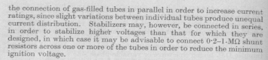
The penalty is noise, and while gas amplified valves were used in audio applications, particularly portable, their home turf quickly became industrial applications where the end result was a binary on/off.
Speed was also a problem due to de-ionisation time which limited most gas valves to high audio speeds. Initially using neon it was found that the inclusion of a few percent of hydrogen greatly sped up de-ionisation and thus valve speed.
Not all gas tubes were cold cathode and hot-cathode thyratrons in particular were used a lot in industry to operate relays directly, and in oscilloscopes as relaxation timebases.
Examples of this line of gas tube development are still all around.
- The humble neon pilot light
- Mercury and sodium vapour lighting, including fluros
- “Neon” signs (different colours come from different gas mixes)
- Xenon camera flashguns
- Disco strobes
- Xenon cinema projector lamps
- Modern car headlamps
- Thyratrons (valve SCR's)
- Ignatrons (really big valve SCR's)
- Geiger-Müller radiation detecting tubes
- Self-illuminating lift buttons
- Telephone lightning arrestors
And of course the voltage regulator tube. Some gasses display a constant-voltage characteristic and this was employed to provide stable voltage supplies, very much in the manner of zener diodes today.
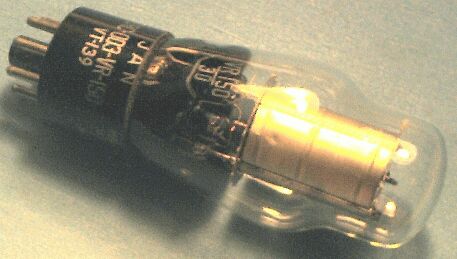
A very simple structure consisting of a cylindrical anode and a straight wire cold-cathode up the centre. The cathode is treated with an emissive coating, but unlike hard vacuume valves these cathodes have to cope with ion-bombardment without being damaged.
The only trick is the striker, a small wire attached inside the anode that ends a few mm short of the cathode. The initial ionisation of the fill gas starts in this gap and provides ions to cascade conduction to the whole tube.
This is VR150 which is, naturally, a 150 volt regulator.
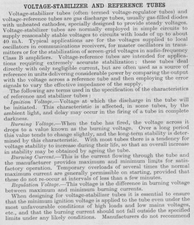
| Voltage | US type | UK type |
| 150 | VR150 | 0D3 (0A2) |
| 105 | VR105 | 0C3 (0B2) |
| 90 | VR90 | 0B3 |
| 75 | VR75 | 0A3 (0C2) |
Pat Hawker takes up the story:
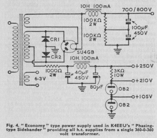
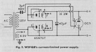
This is an example of a fairly conventional use of VR tubes in power supplies.
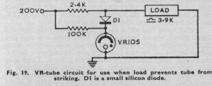
This illustrates the use of the internal base link to protect the regulated circuit should the VR tube be unplugged.
This not only solves a VR application problem, it's a pretty cute little circuit trick. I'll leave it to the reader to work out how this solves the problem.
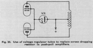
Here the VR tube is being used for a fixed drop from a higher rail. Strauss used exactly this trick in one of their amplifiers.
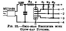
As valves go the glow-gap divider was a rare variant even in its day.
So what's this then? No, not a multi-voltage VR tube but another example of what you can do with gas technology that you can't do with vacuume (or not nearly so easily, anyway).
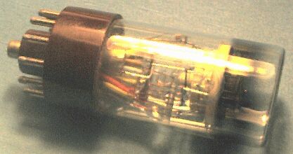
This little baby is a Decatron and was used extensively for industrial counting/display applications such as Bendix batch counters into the 70's. End-viewing, there were generally mounted in a row with their ends poking though the front panel surrounded by a numbered escutcheon.
There are thirty cathodes, ten digits and two sets of guides arrayed in a circle around a central disk anode. The cathodes are ordered Cathode 0, Guide 1, Guide 2, Cathode 1, G1, G2, C2, G1, G2, C3, and so on.
On power-up one of the numeral cathodes strikes and holds the discharge. Reset is by opening all the cathodes except zero, to which the glow will auto-transfer.
To count the first guide rail is pulsed negative, causing the glow to auto-transfer from the cathode to the first guide cathode next to it. This is allowed to go positive as the second guide rail is pulsed low, capturing the glow. When this guide is allowed to go positive again the glow auto-transfers to the next numeral cathode, now being closer than the starting cathode.
Resistors in each cathode circuit allow the detection of a terminal count. These will count up or down so may batch from zero-to-count or count down to zero. These also appeared in scalers, particle counters in neuclionics.
The smoky band on the glass around the cathodes is their main failure mode. Ion bombardment causes the glass to darken and eventually go silvery and hard to see though. Part of the service routine was swapping all the tubes around one (units to thousands, all down one) to distribute this darkening evenly across all the tubes. I encountered these in pill counters where the batch was generally small so the upper tubes didn't get exercised.
Coupling circuits could either be the old faithful 12AX7 or another gas device called a trigger tube, its operation similar to a SCR.
Counting speed was limited, about 10k counts/sec for this GS10C.
Sidebar: Where higher counting speeds were required, such as in neuclionics, another hard-vacuume tube called the Trochotron was used. These are a cathode-ray beam switching device which were very much faster. In some cases these were used as pre-scalers ahead of decatrons.
These consisted of a valve envelope like a 6L6, but with two rows of numbers, odd and even, wrapping around part of the side. In operating the classic blue/green phosphor glow appeared in a window next to each digit, counting proceeding zig-zag up and down, left to right.
Like decatron counters, these also made heavy use of VR tubes for the various supply and bias rails their operation required, the Bendix having about six different supply voltages.
|
|