
|
http://www.ozvalveamps.org/repairs/circuitbin.html | Created: 2011/06/05 | Last update:
2017/12/21
<<< OzValveAmps |
From down the back of the filing cabinet at AVA.
These circuits have been acquired over time, downloaded for repairs in hand, to answer repair questions, or exploring design ideas (an all electronic Lesley rotating speaker effect for one). They are here because they are not of ANZ manufacture and there is no other specific place for them, but they are fairly typical of the sort of thing an amp tech will have coming across the bench.
This is not intended to be exhaustive but only to provide representative examples, particularly for stomps and Fx.
Anyone who wants to add, attribute or remove a circuit should e-mail;
Note: LDR = Light Dependent Resistor, Cadmium Sulphide (CdS) cell
The original used 4558 and 741 op-amps. Today we could use the TL07x or TL08x single, dual or even quad FET input op-amps and improve the distortion and residual noise. While there are super-dooper quiet op-amps available, the LM833 is an almost perfect dual audio amplifier at a very cheap price. Effects oscillators are normally not critical since they aren't in the signal path.
Each of the sections of the chain introduces a phase shift determined by the capacitor and the FET, and this phase shift accumulates down the chain. This basic phase shifting chain is applied in various ways in different effects, ranging from a single shifter to produce a very subtle frequency shift, then adding feedback and multiple paths (plain, or itself shifted as here) and summed to produce selective cancellation at the output, resulting in Vibrato, Phasing, or Flanging.
The little FET matching test circuit in the middle measures the individual FET Idss (Drain current, gate shorted to Source) and applies generally to matching FET's in any phase-shifting network. This matching is needed because most common FET's (such as the common MPF102/2N3819) have a very wide spread of Idss characteristic, often as much as 10:1. The exact value isn't critical, but the Idss should be matched to better than 2:1, and we would generally aim for better than root2 or 1.5:1. Once matched the “trim” control is used to bring them all into an acceptable operating range.
With typical Elektor overkill this circuit has three areas of interest.
The first is the input section which allows the insertion of small capacitances across the guitar output. With a naked pickup this will allow manipulation of the pickup self-resonance. This is discussed on the pickups page, and could be used ahead of a valve rather than the FET shown.
The input amplifier or impedance converter around the FET is an example of an idealised stage using a current source and current sink.
The enhancer itself allows a controlled small amount of distortion due to diode D1 to be added to the clean signal. While this looks similar to a fuzz circuit the signal level across the diode is quite small and only works it across its initial non-linear curve, producing only a light distortion.
An indicator is also provided to assist in the correct setting of the enhancer controls.
function-gen - ECELab.com
Four op-amp fixed frequency function generator/oscillator with square, triangle and sine output.
Two op-amp tuneable function generator with square and triangle output. The main attraction of this sort of function generator is that it is tuned with a single resistive element which may be a FET or LDR. Switch selecting values for C1 allows range switching.
Harmoniser - More Elektor overkill with this circuit that is a stereo form of the enhancer
This extracts higher frequencies from the signal passing through and using diode distortion adds harmonics to it, but is gated so this only happens when the signal is above a set level.
The rank of op-amps on the right side are configured as gyrators or simulated inductors. These act as series-resonant LC circuits with C10 etc taking the role of the C and the op-amp and C9 etc setting the value of the simulated inductance L. Each acts as an acceptor resonator in its band, and the dip in impedance is fed via the control to the main amp feedback circuit, giving boost or cut.
This gyrator circuit element is important to understand since it is used almost univerally in multi-band graphic equalisers, so common in fact that there are specific multi-section IC's specifically for this application.
jordan_bosstone N.B. value corrections. Values on the circuit disagree with values in the parts list. R2 should be 150k, C3 should be 47 or 50pF, R7 should be a 10k pot. R2 is quite “tweekable” and trying different values down to 68k may be profitable. I'm also inclined to think that R6 should be between +9V and the emitter of Q2 since the circuit seem unstable and prone to self oscillation as drawn.
This is a fairly conventional high gain amplifier followed by a diode clipper, but note carefully that the two back-to-back diodes are not the same type. This is deliberate so that the signal clipping is slightly different for the positive and negative signal peaks, as it would be in an overdriven valve preamp.
IC4d - high impedance input buffer, IC4a - signal polarity inverter, IC6b - three pole low pass filter, IC6b + IC3c +IC3? - signal slicer, the first flip-flop IC1 is a squarer, the second flip-flop is the actual frequency divider. This divided signal is injected into the gain control port of an OTA IC2f, 13600, which is also fed with the unconditioned signal input, which is therefore modulated by the divided signal.
Simple, modulated Twin-T filter, LDR bypass switching.
A fairly conventional valve guitar preamp with gain, volume, treble, bass and middle controls, but also featuring a “sweep” control that allows some adjustment of the hinge, or turnover, point of the tonestack from around 500Hz to around 800Hz.
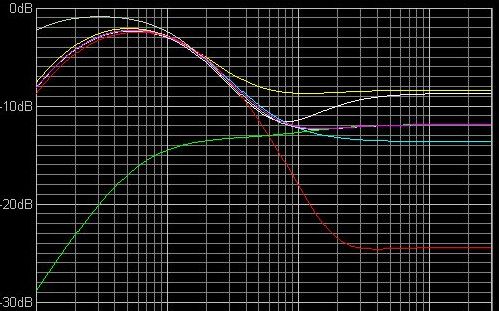
Sweep at minimum 10k
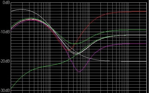
Sweep at maximum 110k
Response graphs from Tone Stack Calculator
Op-amps A2, 3 and 4 comprise a state variable filter that has low-pass, band-pass and high-pass outputs, and can be tuned with two series resistance elements.
The mystery component, “OB05” or “O805”, is a LED to dual LDR opto-coupler. One of the LDR's goes between A2 and A3, and the other between A3 and A4.
The light is a LED or LEDs (because filament lamps are polarity insensitive). R23 should be selected to give a LED current of 20mA or less.
A very straight forward distortion pedal suitable for beginner construction, can use just about any available op-amp and the diode clamp can be tweeked to taste. Note: the input tip and ring contacts are drawn transposed; ring is power, tip is signal.
Uses a common LM386 audio power amplifier, a common transistor radio transformer, and full-wave rectifier.
Four stages of heavily clipped gain
Note: the springline driver uses current feedback so the outer of the RCA connectors driving the line must be isolated from ground.
Three simple boosters - bass/treble Big Muff style control, bass booster, and presence control. All of these have quite low input impedance and will seriously damp an unbuffered pickup.
triangle-to-sine converter - Driven by the function-gen above this should provide a variable frequency audio function generator with square, triangle and sine output. While diode wave shapers of this sort can produce a reasonable approximation of a sine output they aren't perfect and contain distortion that may be significant in some applications. Their main attraction is very good amplitude stability when used for frequency sweeping applications.
uniflash Bob Starr again with a complex way to flash a small globe, unless you want tight control for LDR's.
Valve Vibraton - a stand-alone version of the vibrato effect used in Vox AC30's and as Fender's “Harmonic Vibrato”. This design produces selectable vibrato (phase/frequency modulation) and tremolo (amplitude modulation). It is contended by some booters for Magnatone that they produced the first and only genuine frequency shifters. “First” is a matter of history and patent applications which I don't dispute, but “only” is simply a failure of proper circuit analysis since circuits such as this one (apparently inspired by the Vox) do indeed produce a shift in frequency.
Vari-tone-p1 and Vari-tone-p2 - an article by Tim de Whalley on the Gibson Vari-tone which is a passive tunable notch filter that can be applied as a modification to other guitars.
Valve vibrato unit - from RTV&H. Actually an amplitude modulation tremolo unit using a single 12AX7 and neon/LDR.
Z.Vex SHO (Super Hard On) - MOSFET guitar buffer/booster. Layouts by Andrew Carrell for printed circuit, dab-board, or Veroboard construction.
The circuit thanks to Gottfried Divos.
|
|