
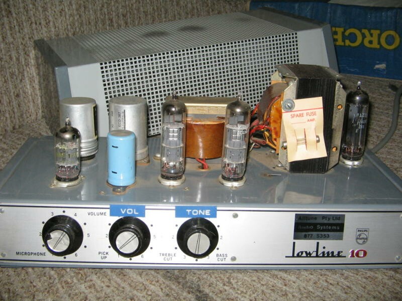
12AX7 into a pair of 6BM8's in push-pull
Outputs are 150, 300, 600 and 1200 ohms (100 volt)
|
http://www.ozvalveamps.org/awa.html | Last update:
19:31 17/04/2012
<<<OzValveAmps |
Amalgamated Wireless Australia, AWA, was a major manufacturer of electronics in Australia, mainly for the broadcast radio sector, but also some more general industrial products. These included amplifiers intended for factory and school PA service. They were taken over by UK firm STC, Standard Telephones and Cables, now part of the French Alcatel group.
Contains:| (AWA) PA774 , PA826 , PA827 , PA828 , PA872 , (STC) PA1001 , (AWA) PA1002BY , (AWA) PA1003Z , (AWA) PS1002 , (Philips) XM392 , (Philips) 957C , (Philips) 961 , Bringing A Really Old Amp Up , (STC) 6CM5 rebuild , (Philips) LowLine 10 , 55W 6DQ6 , Jeremy's “Critter” , AWA Broadcast Monitor Amp |


5 Watt
Model: PA828
Serial: 406
Date: 1960's
Source: Evan Lorden

Circuit diagramme.The amplifier itself is very conventional; 6AV6 mic pre, grampohone pickup input with level and top cut, and two 12AX7 stages into a single 6V6.
The output is arranged to drive 1, 2, 3, or 4 by 600-ohm loads.
The give-away is the power supply, 240VAC mains and 12 volt DC (from a car battery). The tranny has both a 240 volts and 12 volt input winding. The 12 volt DC is chopped by a mechanical vibrator.
So we have a small amplifier that will run from a car battery and drive a few 600-ohm speakers, so it's intended for portable use, and to drive long speaker lines. Obvious uses would be small surf life-saving carnivals, school sports days and the like, driving a few metal horns on poles.
The vibrator itself is a heavily-weighted reed arranged much like a buzzer or bell, with coil and an interrupter contact to make it oscillate.
This carries another pair of contacts that allow the 12 volts to be alternately switched to either end of the 12 volt winding. This is called an asynch vibrator, and has to be followed by some sort of rectifier, in this case the 6X4.
There is another form called the synch or self rectifying vibrator. This switches the high voltage side with yet another set of contacts, making a mechanical rectifier.
There was once a lot of gear around that used vibrators for the HT, including many early valve car radios, grand sets for off-grid farmhouse use (which may be for 24 or 32 volts DC), taxi two-way radios, etc.
Vibrators are prone to contact pitting, but with a little care can generally be wangled open and repaired. Contact timing and adjustment is critical and some care should be taken after a repair that the switching is clean and symmetrical.
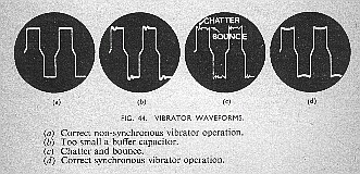
Source: The Oscilloscope Book, E.N.Bradley, Norman Price 1951.At one time there were solid-state replacements available, and in this case it wouldn't be too hard to figure out a suitable s.s. power chopper.
The “standby/operate” switch, S1, turns off the vibrator and HT while leaving the heaters running, as a power economy measure.
New: 21/10/09
Serial: 1981
From Dennis Keath.
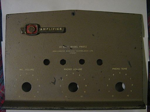
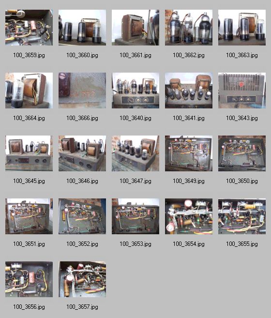
Photos of an AWA PA872 to add to the AWA stuff. Amp was totally shot but the outside was clean so I thought these photos might help someone if they find a cleaner unit to rebuild.
2 x KT66
2 x 12AX7
1 x 5V4G
Like most of these AWA PA's the circuit is printed on the back of the metal case and Dennis has provided shots of the whole circuit, and each of the sections in closeup, power supply, filtering, output1, output2, phase-inverter/driver, mic transformer, preamp, valve layout, and pin connections.
Model: PA1001
Serial: AB 4031
Date: 1960's
From Craig Dean.
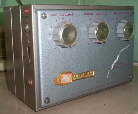
I have just acquired/rescued (via e-bay, $4.99) a 1960's school/auditorium 100w STC valve amp model PA1001. It's a rebadged AWA, the original AWA logo is still visible under the solid black line on the front panel.
Photos are of its initial condition prior to replacement of most of the caps, suspect resistors and damaged wiring.
The corrosion on the power and output transformer turned out to be only relatively benign surface corrosion, so the $5 bet paid off well.
It now works with some minor tweaking and fault isolation still required, (a minor HT insulation breakdown of one of the connectors or wires, residual AC ripple, and fitment of suitably matched EL34's). Alternatively it can be fitted with 6L6/KT66's.
I plan to use it as a guitar amp for the time being while I decide how best to restore it.
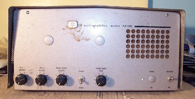
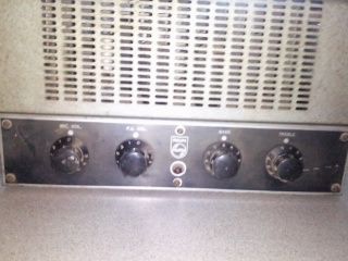
The control line-up is very typical of PA's for factory and office service. In this case it has two microphone inputs with volume controls.
Next is a volume control for the Phono-Radio input. This reflects the common practice of feeding a tuner or record turntable (phono) into the PA for background music, “BGM”, between announcements.
The Radio input connects to a socket under the chassis and Phono to a socket on the same side as the mic inputs.
Generally these amps were installed somewhere in the office, frequently at the front reception desk, and it was not unknown before the days of Muzac™ for the receptionist to double as the factory DJ, changing records.
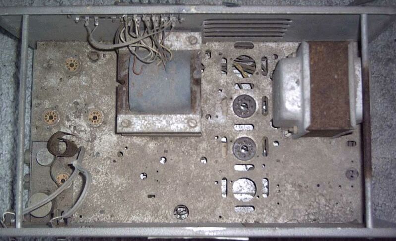
The dimples are plugs in holes. This indicates that the basic chassis metalwork was also used for other models with different facilities, perhaps one with a built-in radio tuner.
The switch selects either the Phono (turntable) or Radio input.
The tone control would apply to the BGM but not the microphone inputs, and would normally be a simple top-cut type control.
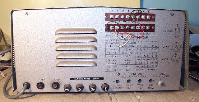
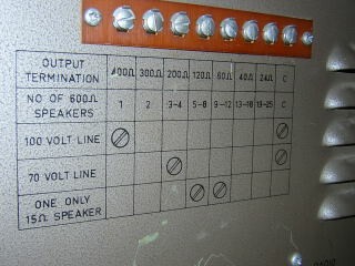
The terminal strips are to select the required output impedance and to connect the speaker circuit(s). The required strappings are shown in the table. In a large installation this may be 100-Volt Line. Note the terminals, upper right, marked “A” and “E”. These also suggest a model including an AM tuner, being the Antenna and Earth terminals respectively.
The Dymo™ tape marking gives away the four cathode fuses as a retro-fit. Cathode fusing is not a good idea.
The Output Limiter pre-set may be related to ALC/Ducking.
The next two adjustments are for the bias adjustment to allow idle current setting for each pair of output valves.
The “AC Bal” will be a heater circuit balance or “hum-dinger”. Addendum: 1/1/11 - looks like this might actually be drive balance to the output stage.
Finally a switched bass cut control for situations where the speakers are minimally baffled and excessive bass drive would result on cone flapping on breath-pops, or to cut turntable rumble.
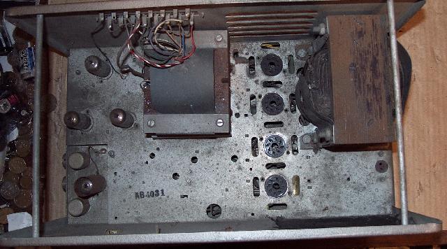
Things start in the lower-left. The screw locking rings for the two microphone connectors can just be seen in the left side.
The first stage is built on a sub-chassis often both mechanically and electricially isolated from the main chassis against physical microphonics and hum-loops, generally using rubber grommets as mountings.
The two capsules next to the preamp stage are mu-metal screened isolation transformers for each microphone, typically something like 600 ohms to 10K ohms, and may even provide balanced inputs. Addendum: 1/1/11 These trannies have been reapplied to good effect as isolation transformers in built-in DI outputs. Sometimes the input circuits also bring in a keying line as a contact from a remote mic to allow remote PTT.
The following preamp and phase-inverter stage are above, and in the centre is the output transformer connected to the rear output selectors. Note the “A” terminal isn't connected.
Below-centre are a number of small holes. These may be for mounting of coils when a tuner is included. Note also the underchassis vent slots around the output quad sockets. Passive cooling is still good design and the idea is to use the heat from the output valves to draw air from below chassis.
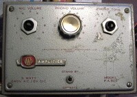
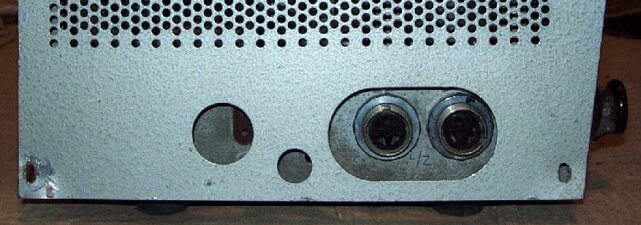
The holes in the front covered with fine metalmesh are actually intended for a small loudspeaker for local monitoring.
The socket far right below the mains transformer is a connection point for such a speaker when fitted.
The switch labeled “Monitor/On” on the far right [front panel] selects the monitor speaker which is connected via the socket on the chassis directly behind this switch. This socket is connected via the switch through a 22ohm resistor to terminal 1 and 12 of the output transformer.
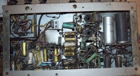
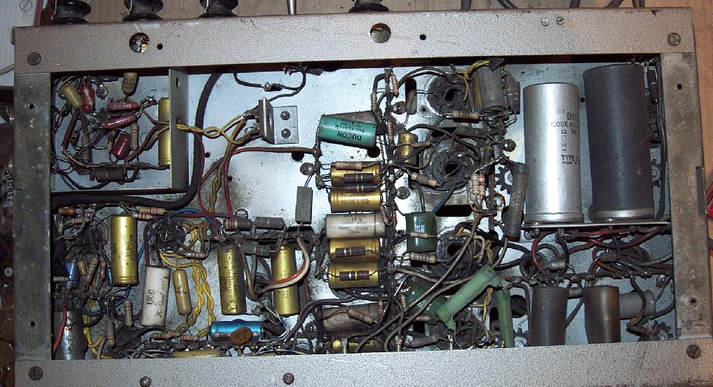
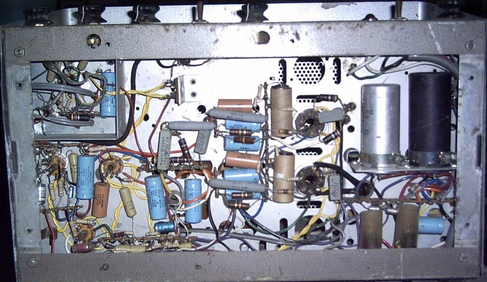
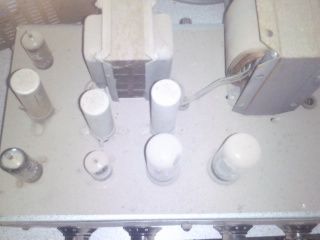
Click for full size 150kb jpg.The deposited dirt maps the convection air flows, and indicates this amp spent a long time operating in one place. Most of the components would now be suspect, particularly the few waxed paper capacitors scattered about. Note the burnt screen resistor on the second output socket from the top, common with a 6CA7/EL34 screen grid failure.
The two larger caps on the right are a voltage doubler network, the power transformer is not centre tapped. The Radio input connects to a socket under the chasis and Phono to a socket on the same side as the mic input.
Similar to Conqueror
50 Watt PA. 2x 6CA7/EL34's(?)
Source: Steve Kain 08/02/06

Clean underchassis, but some of the components may be past it.
Note the burned screen resistors (again) just left of o/p valve sockets; two 47 ohm heater balance resistors on the upper output socket.
One insulated electro, one normal, in series, and two diodes in series below - a doubler HT supply on the right.
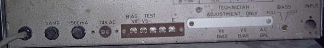
Your guess is as good as mine as to what the 24 volt AC outlet was intended for.
Controls close-up 16kb jpg
New: 29/11/09
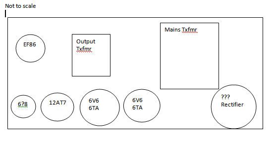
The output valves are 7027A. The other valves are:
And we can ponder for a moment the spare holes for a second pair.
- nearest to the output transformer = 12AX7,
- then two EF86 valves,
- and one 12AX7 near the diodes. This one has a metal shield.
Source: Lucien Buddle
Carl Hirst sent in a circuit tracing quite a some time ago that has been taking a little snooze down the back of the AVA filing system (sorry).
Carl also provided this quote;
“Above all, the humanness of a performer should be apparent... the essence of a living being is greater than the music. The music is only an expression of that essence.” - Barney Kessel
Model: PA1003Z
Serial: DL 7738 - 770
Date: 1960's
Source: Murray and JodiAnother very conventional amp like its kin, but this particular one effectively has the heater for the preamp as the output pair cathode resistor! If this is someone at AWA being very cunning, I'm afraid it totally evades me.
I'd love to know if they are all like this, or only this unit has been modded. m&j have kindly provided a circuit trace, but for once I'm not putting it up until another one turns up like this, 'cause I suspect this one may only be somebody's bodgy fiddling. Addendum: 1/1/11 - Nope, I've since had a report of another like this, so it looks like it was a (highly dubious) design “feature”. This is a good example of bad design, being far too cunning by half.
New: 21/10/09
Source: Derek Lark
Circuits for the full output stage, input circuit 1, input circuit 2, and mods for guitar and PA. (.png's)
Serial: ?
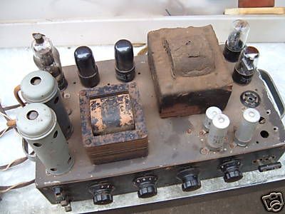
Model: XM392This one is a serious oldie.
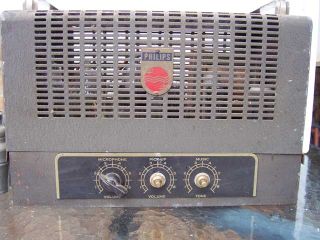
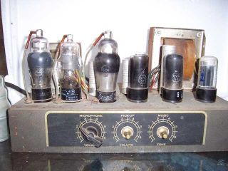
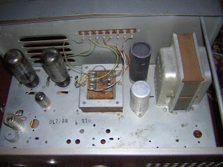
The valve lineup is 6C6 mic preamp, (6C6?) turntable pickup pre, 6C6 PI, 2x 6V6, and 5Y3 rectifier. Note the contour valve can far left. The sockets for the first three valves are mounted off the chassis on rubber grommets to reduce microphonics. The “music” tone control, right, is a simple top-cut type that operates on the pickup input only.
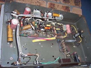
Ugh - paper covered electrolytics and brown waxed-paper caps, all very sus these days. Another vintage feature is the use of resistors with body-end-dot colour codes. Note the cooked power resistors, right. Along the bottom, from left, is the octal microphone input, octal pickup input, power-outlet-like 2-pin output connector which suggests 100V line rather than speaker impedance, and fuse holder. Screened lead with exposed braid was very common in the era.
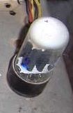
This is a closeup of the 5Y3 rectifier, and it's dead-e-bones. The first clue is the white cap rather than the silver of a healthy “getter”. By itself this is a giveaway of a gassy valve. But of we want confirmation we can tell the power is on by the blue glow at the bottom of the left anode. Be warned - operating an amp with a gassy rectifier like this will quickly lead to an over-heated reccy and endanger the power transformer.
Source: Nigel Fairclough
New: 23/10/09
Nigel's entire photoessay (click to download Zip) . . .
New: 30/6/11
Roger writes;I?m an old electronic tech (I did valve theory in my apprenticeship). I am also a learner guitarist, and have been looking for a valve amp. Hell they hold their value!
Anyway I found an old amp in the back of a factory, the old P.A. I guess.
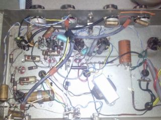
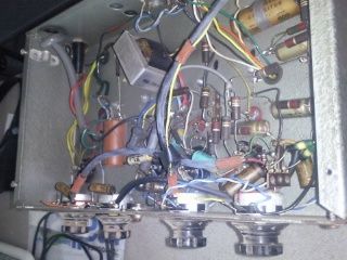
And Tim Robbins is getting in on the act with his Philips 961, serial 3486.
Two microphone and one P.U. input channel PA amplifier. 9-pin pentode amplifier for each microphone channel, and for summing amplifier. 6SN7 splitter and fixed bias push-pull pentode output, with secondary side feedback.
Plate supply from half-wave voltage doubler 5U4GB (2x) diode rectifier and capacitor filter, inductor feed to the screen supply, and resistor dropping to the driver circuit supplies. Output stage grid bias from separate half-wave diode supply (can't determine valve type used). Bass & Treble tone pots between summing and splitter stages. 5x 8-pin Octal and 4x 9-pin Novel bases total.
Power and output transformers with markings but no manufacturer. Choke from Plessey. POTs are IRC but only BD2 or RC2 markings. Ducon caps. The 20uF is DUCONOL A. 330V secondary will likely supply about 800V to output stage.
Modified over the years: voltmeter on cover; most supply rail caps bypassed; extra P.U. input added and associated volume pot added to front panel.
All transformer windings and choke show good Megger readings. However the amplifier was not powered up in original circuit due to condition of all caps. The amplifier is presently undergoing a complete rewire, with the circuit changing to guitar amplifier use.
Tim's photoessay . . .
Bringing a really old amp up
Update: 18/8/08Here is another take on how to bring an old amp up safely. I have added a few points, but basically this is a post from "6267" at the Music Electronics Forum that I thought was worth repeating.
“WebMentor” a.k.a Nigel wrote to me, sending pix of an amp he has obtained, asking my opinion on restoring it. It's a factory-PA style of amp typical of many similar that Philips and AWA were knocking out in the 1950's and 60's, this being one of the earlier Philips builds.
The basic question being asked was - is an amp this old (e.g. 1950's build) worth restoring for guitar service?
Points worth considering are,
Is it a classic that should not be restored?
Generally the older an amp is, the more the scales tip in favour of “glass-casing it” - restoring it visually as a non-working exhibit. 1940's or earlier you want to have a long careful think before attacking it with your soldering iron.
The general rule is do no harm - nothing you can't undo such as drilling or cutting. Replace duff components with new ones, but take pix first, and lable and stash the old components. Leave old can electro's in place and rewire to new ones hidden underchassis.
How much needs to be renewed?
First it needs to be restored/repaired to original standard (or for mains wiring, an acceptable standard). In an amp of this vintage you can assume that all the HT can electro's and waxed-paper caps are history, and can be replaced en-masse.
Valves, particularly preamp valves, can be quite surprising after a good clean up of the pins and socket contacts. The output valves may be weak but still functional, and this particular rectifier has tossed the towel in.
But when you see body-end-dot resistor markings like these, you know that every single component will need to be looked at quite closely before you can be sure that it's really healthy.
How much needs to be modified for gigging guitar service?
These amps were built as factory PA's and thus the control facilities fitted were quite a bit different to guitar amp use.
The inputs were generally via two- or three-pin mike sockets, and an octal (o.n.o.) connector for a radio tuner and/or turntable for BGM, BackGround Music.
Apart from the connectors, the mic input is normally only a few tens of mV and tends to be over-driven by a guitar, while the aux inputs were a volt or more and therefore tend to be insensitive for guitar.
The most common problem however is that as factory PA's these type of amps typically had an output transformer intended to run high impedance “volt-line” such as 150, 300, 600, and 1200 ohm line (a.k.a. variously known as “70-volt line”, “100-volt line”, etc; not to be confused with line level aux inputs)
How to connect a low-impedance box such as 4 or 8 ohms?
There are two possible pathways here.
The first is to replace the output transformer with one that has suitable low impedance windings (this will be more difficult where a tertiary NFB winding has been used).
The second is to do what was originally done, and fit a suitable line-to-speaker step-down transformer between the existing output transformer and the required low-impedance speakers.
Altronics and WES both carry suitable inexpensive transformers.
All-metal amps such as this don't “road” well and really need the protection of a wooden case to prevent metal crimples in corners and such when they are dropped, and on the road, everything gets dropped at some point. Wood is more forgiving than sheet metal.
“6267” power up thoughts
{worth quoting; my emph and comments}
“6267” posted on Music Electronics Forum at 04-25-2008, 08:50 AM
I would follow all of the recommendations, recap, check resistor and cap values (this will be tedious, you could just recap and power it up on a non-conductive surface using a ten foot pole and eye protection :) ).
I'd pull all the tubes the first time.
Find a way to ground (securely) one lead of a DMM. Set it to the highest AC volts setting, and with one hand in your pocket, check the volts between the metal chassis and ground (no tubes).
Chassis to Mains Earth, plug wired correctly; a known good neon screwdriver is also useful for detecting dangerous voltages
This should be 0 or damn close to it, like 0.024. As long as this is zero, switch the DMM to the highest DC volts setting, and check the chassis to ground. This is generally between 2 and 0 volts, and I wouldn't expect to see much more than 6 accounting for variations in ground etc.
If the chassis is free of voltage, unplug it, relax, and come back later. There is hope! Now you are going to want to go to www.tubedata.org and look up the tubes in the amp.
Turn it on with the aforementioned non-conductive pole, (a cheap all plastic pen will work ok, as long as it's dry). Again, check the chassis voltage is zero, and using the pinouts from the datasheets, again using one hand, you might try verifying that voltages are present where they belong. Everything will measure too high, but what you are checking is that the power supply is not short etc.
Heater voltages will sometimes require measuring between two pins in a socket. For this, turn the amp off, insert the probes, set the meter, and turn the amp back on for best safety.
They will often measure very high with no tubes in the amp, but not more than a few volts higher (i.e., 7-8 for a 6.3v heater). If there is B+ and heater voltage to all tubes, you may be very close.
Replace all the tubes (perferably tested on a tester first, some old electronics stores have these still, thankfully). Using an old power cord, wire a 470ohm (this should work without any input, for either 8 ohm or 70v for a short period of time) 5-10w resistor across the end without the plug. Put this in the speaker jack.
The amp should certainly have some sort of load resistor across its output, best the correct load if known. But I'm more gradualist about re-inserting valves and do it in stages.
Using the non-conductive pen, flip the amp on, but be ready to flip it off after anything strange happens. If the tubes just light up and nothing sparks, arcs or catches fire, you may be in luck.
This is known as the “smoke test” - switch it on and see if the smoke comes out. I'd take a gentler hand with an amp of this vintage; load limiting lamp and such first.
Turn it off and check the voltages on the chassis again for safety. www.radioremembered.org/outimp.htm will explain how to test the transformer after it has been disconnected.
If the voltage ratio is a 500-2k:1, you probably have an 8-ohm output. If it's a lot less, it's probably a 70v transformer. Some transformers have other output wires, so you could conceivably find a different tap inside the amp for 4,8,16 ohms.
I have a 60s PA that does this. If there is only a 70v tap, use an appropriate edcore, Hammond, or other output transformer in its place (it'll wire up similarly and not require much more than soldering/bolting). Some of the Fender replacement parts would work here and are available for less than $50 USD.
See also The Lamington - Bringing the amp up.

This amp sounds incredibly nice. It's been fully rebuilt and reconditioned by an experienced tech, and is ready to give years of service to the tone-conscious guitarist. Truly a match for any 'boutique' amp, but a genuine hard-wired article from the '60s, not a modern clone.
The tech who rebuilt this amp says;
The STC amp has been modified and has received outstanding appraisal from one of Adelaide's old guitarists. He said that this amp performed much better than his American amp which used 6L6's in push pull ! I was truly appreciative of his comments.
This one is an almost identical circuit to the Playmaster. There are two 6CM5 high mu pentodes in the output, an EF86 preamp and a 12AT7 phase splitter. All standard guitar and speaker jacks. Controls are on/off switch, pre-amp gain, main gain, and tone control. There are two spare NOS 6CM5's also plugged into the chassis, and they are included. The output specs quickly, 50Hz 25W and 1kHz 38W
Source: Neil Rote, Grouse Guitars
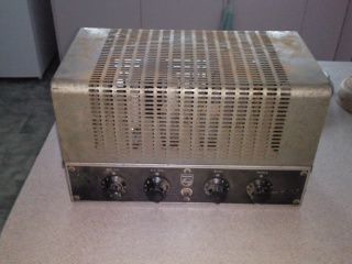
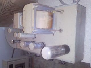
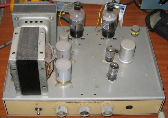
Source: DunxyAnother small factory PA using 6GW8's (centre) for about 10 watts out.
The thing that looks like an upside-down film can with an octal base, left rear, will be the microphone input coupling transformer.
Note the blackening on the rectifier glass envelope, far right. This is caused by a long period of electron bombardment and is the sign of a valve that has been in service for a long time. In extreme cases this darkening will become silver, a bit like the getter.
It means the valve is old but I've seen equipment with dozens of 12AX7's like this still working fine.
Source: Dunxy
New: 24/7/09
Model: unknown
Serial: unknown
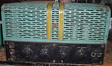
Phillips valve amp
hi,
i recently brought this phillips valve amp from ebay in not working condition and are looking to restore it for use as a guitar amp, unfortunatly i have been unable to find any information about this amp and was wondering if you may know of it? any information you may have would be very appreciated.misc info
2off 6v6gt
2off 6c6
1off 6x5gt
2 unknown (no markings)
1 empty slot
2 inputs mic and pu and gain dial for each
tone dial
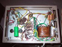
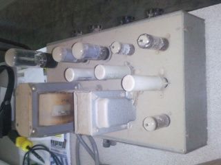
Note the empty 6-pin vibrator socket middle-rightI replied...
Gee, that one's a real blast from the past!
I'm afraid I can't tell you much from the pix but a clear underchassis shot might help.
Specifically the empty socket may be for a "vibrator", a mechanical buzzer-like device used in the early days in equipment intended to run from low voltage DC (generally 12 volts), and any signs of say connections for a low voltage DC input on the rear would tend to confirm that. Many of these really early (1940/50's) PA type amps were built to run on both 12 volts DC (for PA at surf carnivals and the like) and 240V mains. The coupled main switch also points in the direction of a dual supply unit.
Generally speaking an amp of this vintage will at the very least need new electrolytic capacitors (e.g. the silver cans near the front-right) and doubtless a few resistors and such underchassis as well, but the valves themselves may still be okay.
A possible difficulty with an amp of this type is that they often had a high impedance (“ohmage”) output. Many also had a low impedance output, 8 or 15 ohms, but if it's high impedance only you will need a suitable matching transformer to drive normal speakers. While these are available from Altronics for around $20 it's a bit of a pest if you can't fit it inside somewhere (details)
Restoration of an amp of this vintage is a fairly major undertaking, but with care is quite possible. I would urge you NOT to power it up until it has been given a good going over first (to avoid damaging the transformers).
Source: Jeremy
New: 20/8/10
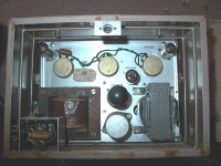
Somewhat different to the normal run of AWA's that turn up, this is a broadcast monitor amp, model number unknown, typically used around AM radio stations and transmitters to provide a monitoring audio feed of the outgoing signal.
The valve line up is 5U4G, two 6V6GT, two 6SN7GT.
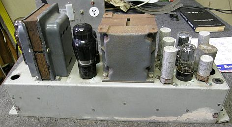
Source: Trevor Currie
|
|